|
|


 Arabic
 Bengali
 Chinese
 English
 French
 German
 Hebrew
 Hindi
Hindi Italian
 Japanese
 Korean
 Malay
Malay Polish
 Portuguese
 Spanish
 Turkish
 Ukrainian
 Vietnamese
|
PERSONAL TRANSPORT: GROUND, WATER, AIR
Farm truck. Personal transport
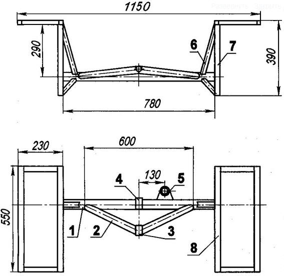
Directory / Personal transport: land, water, air I am a longtime reader and regular subscriber of the "Modelist-constructor" magazine. For almost forty years, he not only got acquainted with the machines and mechanisms of amateur designers, but also created his own. Therefore, I can classify myself as a cohort of "homemade" with experience. He built mainly land-cultivating and transport equipment (from motoblocks to jeeps). I dismantled or remade something from what was created earlier, sold some, and still operate some, for example, a mini-tractor (or rather, a self-propelled chassis), the design of which I present to the readers. The chassis is designed to transport various goods for home gardening (both in its own body and in a towed trailer), and in winter - also for snow removal using a front-mounted bulldozer blade. Description of the design will start with the frame. It is welded mainly from round steel water pipes. In plan (top view), the frame has the shape of an elongated trapezoid with a large base in front. The frame is based on two straight parallel spars made of a pipe with an outer diameter of 42 mm and a wall thickness of 3 mm. A pair of front crossbars is made of the same pipe: the first is solid, and the second is made of three parts. At the rear, the spars are connected by three short crossbars. The remaining parts of the frame are made of a thinner tube - with an outer diameter of 32 mm and a wall thickness of 2,5 mm. Auxiliary elements (racks, struts, struts, etc.) are made of round pipes 22x2 mm. Various brackets for mounting units and assemblies are made of suitable rolled steel. For the most part, they were welded to the frame "in place" during the assembly of units and mechanisms of the structure, and therefore the frames are not shown in the drawing.
Between the front crossbars at the ends, two brackets are welded, made of a U-shaped profile 50x25x50 mm. The hubs of the front drive wheels are bolted to them. Ribs (from a 25x25 corner) of a frame box are welded to the spars for installing the final drive gearbox. Brackets of a U-shaped profile for suspension of the rear axle are welded to the rear crossbars, and two more lugs forming a forkop are welded to the closing brackets, which allow using the crossbar at the back. On top of the frame (approximately in the middle of its length), a steering column with a bracket for the headlight is fixed by welding, and in the rear part, the legs and frames of the seat and its backrest. The upper (horizontal) part of the steering rack - the jumper is made of a wide channel - it serves as a dashboard. From below, in the front part, hanging moldboard racks with eyes (reinforced by struts) are welded, to which a bulldozer blade is suspended.
Later, brackets for the handle of the cable winch for lifting (lowering) the blade, the levers for switching the reverse and the mechanism for preventing tipping (locking) of the body were welded to the steering rack in place. The mechanism itself is a lever with a groove that goes beyond the protruding shelf of the corner of the body frame, and a locking button. I pay special attention to the necessary reliability of the entire assembly - spontaneous tipping of the body on the move threatens with big troubles, especially when driving downhill. Under the rack between the spars on two brackets, the steering mechanism from the FDD motorized stroller is fixed.
as a chassis power unit, an engine from the Izh-Planet-3 motorcycle with a power of 18 hp was used. His cylinder was equipped with a homemade forced air cooling device with an 8-blade fan in the casing. The fan is driven into rotation from the elongated crankshaft of the engine through a V-belt transmission (from the washing machine). The engine is located under the seat, and it is attached to the frame through special welded brackets, which allow it to be moved with a screw to tension the transmission chains.
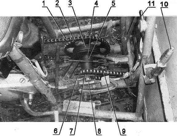
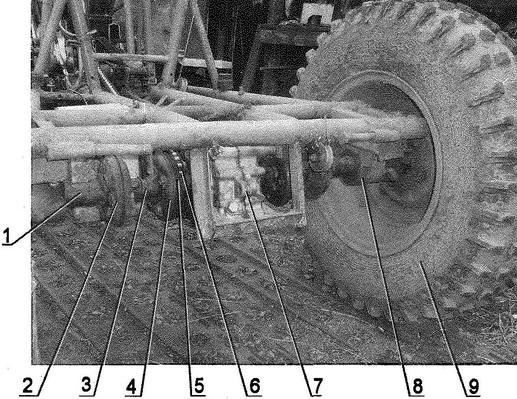
The operation showed that the engine does not need a decompressor now, it is enough to monitor the cleanliness and serviceability of the fuel system and carburetor. Engine failures due to lack of spark in the glow plug have virtually disappeared, which used to be common. The fastening of the interrupter board has also been changed - now it is mounted on the generator shaft in a sliding fit and can be rotated at a certain angle, thereby regulating the ignition. The breaker board is attached to the generator stator with elongated screws, which are then fixed with wire brackets soldered to them. Owners of single-cylinder "izhs" are well aware of the reverse blows of the kickstarter lever, which sometimes leads to serious injury. This alteration completely eliminates this unpleasant phenomenon. Before starting the engine, the board is switched to "late" ignition with the help of a lever, brought out through the generator casing, and after the engine warms up, it returns to its place. On the lever, at the point where it exits the generator cover, there is a locking flag, which with its protrusion falls into the groove on the cover, thereby ensuring a stable position of the board lever at the desired ignition angle. To fine-tune the moment of breaking the contacts of the breaker, the flag is made movable. According to this principle, all single-cylinder "Izhey" engines that I use have been redesigned. The muffler was used from the Buran snowmobile, it is compact and quite effective. Exhaust pipes with union nuts from Izh-PZ are welded to the standard muffler inlet pipes. Since the engine is located at the rear of the chassis frame, and the drive wheels are front, the transmission of torque from the power unit to the main gear had to be carried out through a two-stage chain drive with an intermediate gearbox. Chains are widened, combine. From a combine and a large (Z = 53 teeth) sprocket on one end of the intermediate shaft. At the other end of the shaft, an asterisk Z = 15 is installed from the rear wheel of the Izh motorcycle. In addition, a brake drum (welded to a motorcycle sprocket) from the wheel of the Vyatka scooter is mounted on the intermediate shaft. The brake cover is homemade, and the pads are standard scooter ones. The shield is attached to the frame through two brackets in the form of paws. At the same time, the possibility of orientation (small movement and rotation) of the shield with pads relative to the drum is provided. The intermediate gearbox itself can also be moved along the side members of the frame to tension the chain going to the main gear. The main gear (or reverse gear) was used from the cargo scooter "Ant". It has been modernized: instead of the regular narrow gears of the differential and reverse gear, widened wheelchair-mounted FDDs have been installed. Of course, if you strictly monitor the weight of the load every time and do not abuse the traction forces of the power unit (and, by the way, it is also capable of heavy loads), then these alterations of the reverse gear are not required. The drive sprocket of the main gear (it is also the driven sprocket of the second stage of the chain drive) is also taken from a wheelchair. In principle, the reverse gear can also be used from the FDD stroller. However, it has a parasitic reverse gear mounted on the shaft on a plain bearing (bronze bushing). With intensive use of the reverse gear (which is not uncommon for home use of the tractor), such a bearing quickly fails, and it is better to immediately replace the bushing with a rolling bearing. The transmission of rotation from the main gear to the drive wheels is carried out through a pair of rather sophisticated semi-axes, each consisting of two standard elastic cardan joints with a short splined shaft between them, with a segment of the splined coupling welded to the second joint (closest to the wheel), connected to the hub shaft. The last parts (splined coupling, shaft and hub) were used from the launcher of the DT-75 tractor. A flange with studs for fastening the drive wheel is welded to the end of the hub shaft. Of course, the axle shaft is rather complicated, and if, for example, an elongated hub is made, then the second hinge is not required. But I proceeded from what was available. The front drive wheels are used from a UAZ car. But their tires have been modified into a deep “checkered” for better grip on arable land, off-road and in muddy conditions. At the same time, the tires have also become much lighter. I think that these tires are very suitable for all-terrain vehicles. The technology of their manufacture is described in No. 9'2008 of the "Model Designer". The rear axle of the chassis has the shape of an isosceles triangle, because two identical struts from a 42x3 mm pipe with a sleeve at the vanishing point are welded to the beam (32x2,5 mm pipe). Exactly the same sleeve is also in the middle of the beam on top. Through these bushings, the rear axle is suspended on the frame brackets using cotter pins. Such a suspension allows the rear (and front) wheels to copy the track profile well without twisting the frame, and does not allow any of them to hang over the recesses. At the ends of the rear axle beam, racks from a channel are mounted, to which the steering knuckles are attached, and brackets from the corners are welded to the racks from above for the installation of rear mudguard wings here.
To the beam of the rear axle, to the right of the middle, a glass is welded, in which an L-shaped lever is mounted on bearings, one end of which is driven by a longitudinal rod from the steering rack, and the other end moves two transverse steering rods of the corresponding wheels. Due to the large travel of the beam when the tractor is moving along difficult sections of the track, the diameter of the rear wheels cannot be increased without increasing the width of the rear axle due to the mudguards resting on the engine at extreme positions.
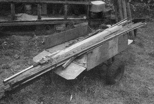
The tractor body is welded. Its frame is made of various corners and sheathed with sheet steel 1,5 mm thick. All corners on the top of the body are rounded to prevent injury. Approximately 1/3 of the length of the body from the front side, two bushings are welded from below to the transverse corner of the frame, with the help of which it is suspended through the pins to the lugs welded to the first cross member of the tractor frame. The fenders of the front drive wheels are welded directly to the body, they have several functions - they expand the loading area, serve as splash protection and increase the rigidity of the body itself, since the tractor sometimes has to carry significant loads. For transportation of bulk materials, I place most of the volume on the front of the body, which allows it to be easily tilted forward almost vertically without additional devices. The sloping front wall and inward-mounted mudguards help to discharge materials almost completely, especially when the tractor is reversed. Electrical equipment is standard six-volt. Established also a carburetor and an air cleaner. The ignition switch connects the battery at the same time. Here on the shield is a toggle switch for turning on the headlight and taillight. It also has control lamps for "neutral" and generator operation. Also increase safety and reflectors mounted on the body. Controls include pedals: gas, brake and clutch. It should be noted that the "gas" pedal is additionally spring-loaded: this is necessary for more precise control of engine speed in dirty conditions and when driving off-road. On the shield in front of the steering wheel there is a reverse control lever. Through two rigid rods and an intermediate L-shaped lever mounted above the steering gear, the reverse gear is switched. The lever itself on the reverse is spring-loaded for better fixation in extreme positions in shaking conditions. The manual winch for lifting and lowering the blade is a roller with a small drum with cheeks that prevent the cable from coming off. The roller rotates in a glass with bearings, the glass is welded to the headlamp bracket. The winch control handle is pressed by a leaf spring against a gear wheel welded to the cup-hub of the roller, and serves to lock the handle with a tooth that enters the gear cavities (the gear itself is from a children's bicycle). The cable is wound on the winch drum through a roller installed at the bottom at the edge of the body and then through the same roller located on the first cross member of the tractor frame, it pulls on the blade frame cross member. The blade is suspended to the tractor frame in two brackets-ears of hanging racks. To do this, there are bushings at the ends of the suspension stops of the blade, which are inserted into the lugs of the brackets and are fastened here with pins with a cotter pin. The blade itself is simple, I just want to note that an increase in its mass is undesirable - this leads to an increase in efforts on the handle of its rise. For this reason, the suspension stops with crossbars that make up the blade frame are made of thin-walled pipes, with the exception of the lower corner of the main crossbar, and the shield is made of duralumin. Removable rubber strips are attached to the bottom of the blade, they have a 30 - 40 mm outlet from below to mitigate impacts on bumps. In the upper position, the blade is pressed against the body and does not sway when the tractor is moving. Of course, with the blade installed, the body can no longer tip over, but in winter the transportation of bulk cargo is extremely rare, and if necessary, the blade can be removed in five minutes. For better grip of the wheels when clearing snow, ballast (20 - 30 bricks) is placed in the body. You can also use snow chains. As mentioned, the driver's seat reclines to provide access to the spark plugs, tool box and spool, as well as making it easier to access the carburetor. In the same place, inside the seat frame, a standard relay-regulator and a terminal block are fixed. Behind the seat on a plate bracket welded to the seat frame, a 6-liter fuel tank is fixed with clamps. Fuel supply - by gravity, through a standard faucet. Kickstarter lever from Izh-Jupiter, it can be folded without interfering with the driver to shift gears with an elongated lever. The lever of the fuel corrector is mounted on the vertical pipe of the steering rack, the drive from the corrector to the throttle valve of the carburetor is by Bowden cables. The clutch pedal is connected by a rod to the L-shaped lever, the lever pulls the clutch release cable with its other end. The brakes are actuated from the pedal through two rods with an intermediate link. Both rods are adjustable in length. To replace the pads, the brake cover can be moved along the second link pipe. In conclusion - about the features of the chassis control. You should not brake hard, which leads to peak loads in the transmission. Spiked tires in summer have high grip (especially on a loaded tractor), and the brake drum is easily blocked. It is dangerous to maneuver in reverse at high speed: with rear-wheel steering, the “steering feel” disappears. It should be borne in mind that the reverse gear is noticeably faster than the front one, and therefore, there is less traction. On loose soils, an unloaded tractor can burrow on slopes. In such cases, you should move in reverse or put ballast in the body. The dimensions and maneuverability of the tractor allows it to "squeeze" literally into any "gap", and unloading forward by tipping the body and further retreat back are very convenient in a private courtyard, where, as usual, the entire area is used to the maximum. The low height of the body from ground level is convenient for loading and unloading, and the low center of gravity contributes to the stability of the tractor on slopes. The mini-tractor is also capable of towing a trailer with a carrying capacity of up to 500 kg. The front and rear sides of the trailer are folding, so it can also be used as a dissolution for transporting long loads.
I tried to hang a plow on the chassis and plow. It turned out well. But I also have a motor winch for these purposes. Author: A.Koksharov
▪ ski bike ▪ Aquaped
Machine for thinning flowers in gardens
02.05.2024 Advanced Infrared Microscope
02.05.2024 Air trap for insects
01.05.2024
▪ Powerful energetic light of the Sun detected ▪ China already has over 1 billion mobile subscribers ▪ Miniature sensor with radar technology
▪ section of the site The most important scientific discoveries. Article selection ▪ article Ecology of urban population. Basics of safe life ▪ article Siberian cedar. Legends, cultivation, methods of application ▪ article Bimetallic thermostat. Encyclopedia of radio electronics and electrical engineering
Home page | Library | Articles | Website map | Site Reviews
www.diagram.com.ua |


 See other articles Section