|
|


 Arabic
 Bengali
 Chinese
 English
 French
 German
 Hebrew
 Hindi
Hindi Italian
 Japanese
 Korean
 Malay
Malay Polish
 Portuguese
 Spanish
 Turkish
 Ukrainian
 Vietnamese
|
Lecture notes, cheat sheets
Database. Entity class relationships (most important)
Directory / Lecture notes, cheat sheets Table of contents (expand) Lecture No. 12. Relationships of entity classes So, all the concepts we have gone through, namely diagrams and their types, multiplicities and types of relationships, as well as types of key migration, will now help us in going through the material about the same relationships, but already between specific classes of entities. Among them, as we shall see, there are also connections of various kinds. 1. Hierarchical recursive relationship The first type of relationship between entity classes, which we will consider, is the so-called hierarchical recursive relationship. At all recursion (or recursive link) is the relation of an entity class to itself. Sometimes, by analogy with life situations, such a connection is also called a "fish hook". Hierarchical recursive relationship (or simply hierarchical recursion) is any recursive relationship of the "at most one-to-many" type. Hierarchical recursion is most commonly used to store data in a tree structure. When defining a hierarchical recursive relationship, the primary key of the parent entity class (which in this particular case also acts as a child entity class) must be migrated as a foreign key to the mandatory non-key attributes of the same entity class. All this is necessary to maintain the logical integrity of the very concept of "hierarchical recursion". Thus, taking into account all of the above, we can conclude that a hierarchical recursive relationship can only be not necessarily non-identifying and no other, because if any other kind of relationship was used, Null values for the foreign key would be invalid and the recursion would be infinite. It is also important to remember that attributes cannot appear twice in the same entity class under the same name. Therefore, the attributes of the migrated key must be given the so-called role name. Thus, in a hierarchical recursive relationship, the attributes of a node are extended with a foreign key that is an optional reference to the primary key of the node that is its immediate ancestor. Let's build a presentation and key diagrams that implement hierarchical recursion in a relational data model, and give an example of a tabular form. Let's create a presentation diagram first:
Now let's build a more detailed - key diagram:
Consider an example that clearly illustrates such a type of relationship as a hierarchical recursive relationship. Let us be given the following entity class, which, like the previous example, consists of the "Ancestor Code" and "Node Code" attributes. First, let's show a tabular representation of this entity class:
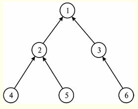
Now let's build a diagram representing this class of entities. To do this, we select from the table all the information necessary for this: the ancestor of the node with the code "one" does not exist or is not defined, from this we conclude that the node "one" is a vertex. The same node "one" is the ancestor of nodes with the code "two" and "three". In turn, the node with code "two" has two children: the node with code "four" and the node with code "five". And the node with the code "three" has only one child - the node with the code "six". So, taking into account all of the above, let's build a tree structure that reflects the information about the data contained in the previous table:
So, we have seen that it is really convenient to represent tree structures using a hierarchical recursive relationship. 2. Network recursive communication The network recursive connection of entity classes among themselves is, as it were, a multidimensional analogue of the hierarchical recursive connection we have already passed through. Only if hierarchical recursion was defined as a "at most one-to-many" recursive relationship, then network recursion represents the same recursive relationship, only of the "many-to-many" type. Due to the fact that many classes of entities participate in this connection on each side, it is called a network connection. As you can already guess by analogy with hierarchical recursion, links of the network recursion type are designed to represent graph data structures (while hierarchical links are used, as we remember, exclusively for the implementation of tree structures). But, since in the connection of the type of network recursion, the connections of the type "many-to-many" are specified, it is impossible to do without their additional detailing. Therefore, in order to refine all the many-to-many relationships in the schema, it becomes necessary to create a new independent entity class that contains all references to the parent or descendant of the Ancestor-Descendant relationship. Such a class is generally called associative entity class. In our particular case (in the databases to be considered in our course), the associative entity does not have its own additional attributes and is called calling, because it names the Ancestor-Descendant relationships by referencing them. Thus, the primary key of the entity class representing the hosts must be migrated twice to the associative entity classes. In this class, the migrated keys together must form a composite primary key. From the foregoing, we can conclude that establishing links when using network recursion should not be completely identifying and nothing else. Just like when using a hierarchical recursive relationship, when using network recursion as a relationship, no attribute can appear twice in the same entity class under the same name. Therefore, like last time, it is specifically stipulated that all attributes of the migrating key must receive the role name. To illustrate the operation of network recursive communication, let's build a presentation and key diagrams that implement network recursion in a relational data model. Let's start with a presentation diagram:
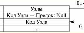
Now let's build a more detailed key diagram:
What do we see here? And we see that both connections in this key diagram are “many to one” connections. Moreover, the multiplicity “0... ∞” or the multiplicity “many” is at the end of the connection facing the naming class of entities. Indeed, there are many links, but they all refer to one node code, which is the primary key of the “Nodes” entity class. And, finally, let's consider an example illustrating the operation of such a type of connection by an entity class as network recursion. Let us be given a tabular representation of some entity class, as well as a naming entity class containing information about links. Let's take a look at these tables. Nodes:
Links:
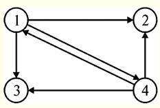
Indeed, the above representation is exhaustive: it gives all the necessary information in order to easily reproduce the graph structure encoded here. For example, we can see without any obstacles that the node with the code "one" has three children, respectively, with the codes "two", "three", and "four". We also see that nodes with codes "two" and "three" have no descendants at all, and the node with code "four" has (as well as node "one") three descendants with codes "one", "two " and three". Let's draw a graph given by the entity classes given above:
So, the graph we have just built is the data for which the entity classes were linked using a network recursion type connection. 3. Association Of all the types of connections included in the consideration of our particular course of lectures, only two are recursive connections. We have already managed to consider them, these are hierarchical and network recursive links, respectively. All other types of relationships that we have to consider are not recursive, but are, as a rule, a relationship of several parent and several child entity classes. Moreover, as you might guess, the parent and child entity classes will now never coincide (indeed, we are no longer talking about recursion). The connection, which will be discussed in this section of the lecture, is called an association and refers precisely to the non-recursive type of connections. So the connection called association, is implemented as a relationship between multiple parent entity classes and one child entity class. And at the same time, which is curious, this relationship is described by relationships of various types. It is also worth noting that there can be only one parent entity class during association, as in network recursion, but even in such a situation, the number of relationships coming from the child entity class must be at least two. Interestingly, in association, as well as in network recursion, there are special kinds of entity classes. An example of such a class is a child entity class. Indeed, in the general case, in an association, a child entity class is called associative entity class. In the special case when an associative entity class does not have its own additional attributes and contains only attributes that migrate along with primary keys from parent entity classes, such a class is called class of naming entities. As you can see, there is an almost absolute analogy with the concept of associative and naming entities in a network recursive connection. Most often, an association is used to refine (resolve) many-to-many relationships. Let's illustrate this statement. Let, for example, we are given the following presentation diagram, which describes the scheme of receiving a certain doctor in a certain hospital:
This diagram literally means that there are many doctors and many patients in the hospital, and there is no other relationship and correspondence between doctors and patients. Thus, of course, with such a database, it would never be clear to the hospital administration how to arrange appointments with different doctors for different patients. It is clear that the many-to-many relationships used here simply need to be detailed in order to concretize the relationship between the various doctors and patients, in other words, to rationally organize the schedule of appointments of all the doctors and their patients in the hospital. And now we will build a more detailed key diagram, in which we already detail all the existing many-to-many relationships. To do this, we will accordingly introduce a new entity class, we will call it "Receive", which will act as an associative entity class (later we will see why this will be an associative entity class, and not just a class of naming entities, which we talked about earlier). So our key diagram will look like this:
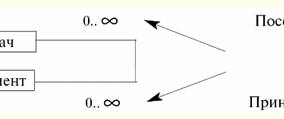
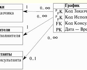
So, now you can clearly see why the new class "Reception" is not a class of naming entities. After all, this class has its own additional attribute "Date - Time", therefore, according to the definition, the newly introduced class "Reception" is a class of associative entities. This class "associates" the "Doctors" and "Patient" entity classes with each other by means of the time at which this or that appointment is performed, which makes working with such a database much more convenient. Thus, by introducing the "Date - Time" attribute, we literally organized the much-needed work schedule for various doctors. We also see that the external primary key "Doctor's Code" of the "Reception" entity class refers to the primary key of the same name in the "Doctors" entity class. And similarly, the external primary key "Patient Code" of the "Reception" entity class refers to the primary key of the same name in the "Patient" entity class. In this case, as a matter of course, the entity classes "Doctors" and "Patient" are the parent, and the associative entity class "Reception", in turn, is the only child. We can see that the many-to-many relationship in the previous presentation diagram is now fully detailed. Instead of the one many-to-many relationship we see in the presentation diagram above, we have two many-to-one relationships. The child end of the first relationship has the multiplicity "many", which literally means that the "Reception" entity class has many doctors (all of them in the hospital). And at the parent end of this relationship is the multiplicity of "one", what does this mean? This means that in the "Reception" entity class, each of the available codes of each particular doctor can occur indefinitely many times. Indeed, in the schedule in the hospital, the code of the same doctor occurs many times, on different days and times. And here is the same code, but already in the "Doctors" entity class, it can occur once and only once. Indeed, in the list of all hospital doctors (and the "Doctors" entity class is nothing but such a list), the code of each particular doctor can be present only once. A similar thing happens with the relationship between the parent class "Patient" and the child class "Patient". In the list of all hospital patients (in the "Patients" entity class), the code of each specific patient can occur only once. But on the other hand, in the schedule of appointments (in the entity class "Reception"), each code of a particular patient can occur arbitrarily many times. That is why the multiplicities at the ends of the bond are arranged in this way. As an example of the implementation of an association in a relational data model, let's build a model that describes the schedule of meetings between the customer and the contractor with the optional participation of consultants. We will not dwell on the presentation diagram, because we need to consider the construction of diagrams in all details, and the presentation diagram cannot provide such an opportunity. So, let's build a key diagram that reflects the essence of the relationship between the customer, the contractor and the consultant.
So, let's start a detailed analysis of the above key diagram. Firstly, the "Graph" class is a class of associative entities, but, as in the previous example, it is not a class of named entities, because it has an attribute that does not migrate into it along with the keys, but is its own attribute. This is the "Date - Time" attribute. Secondly, we see that the attributes of the child entity class "Chart" "Customer code", "Executor code" and "Date - Time" form a composite primary key of this entity class. The "Advisor Code" attribute is simply a foreign key of the "Chart" entity class. Please note that this attribute allows Null values among its values, because according to the condition, the presence of a consultant at the meeting is not necessary. Further, thirdly, we note that the first two links (of the three available links) are not completely identifying. Namely, not fully identifying, because the migrating key in both cases (primary keys "Customer code" and "Executor code") does not completely form the primary key of the "Graph" entity class. Indeed, the "Date - Time" attribute remains, which is also part of the composite primary key. At the ends of both of these incompletely identifying bonds, the multiplicities "one" and "many" are marked. This is done in order to show (as in the example about doctors and patients) the difference between mentioning the code of the customer or the performer in different entity classes. Indeed, in the "Graph" entity class, any customer or contractor code can occur as many times as desired. Therefore, at this, child, end of the connection there is a multiplicity of "many". And in the "Customers" or "Contractors" entity class, each of the codes of the customer or contractor, respectively, can occur once and only once, because these entity classes are each nothing more than a complete list of all customers and performers. Therefore, at this, the parent end of the connection, there is a multiplicity of "one". And, finally, note that the third relationship, namely the relationship of the "Graph" entity class with the "Consultants" entity class, is not necessarily non-identifying. Indeed, in this case, we are talking about the transfer of the key attribute "Consultant code" of the "Consultants" entity class to the non-key attribute of the "Graph" entity class of the same name, i.e. the primary key of the "Consultants" entity class in the "Graph" entity class does not identify primary key already of this class. And besides, as mentioned earlier, the "Advisor Code" attribute allows Null values, so here it is precisely the non-identifying relationship that is used. Thus, the "Advisor Code" attribute acquires the status of a foreign key and nothing more. Let us also pay attention to the multiplicities of links placed at the parent and child ends of this incompletely non-identifying link. Its parent end has a multiplicity of "no more than one". Indeed, if we recall the definition of a relationship that is not completely non-identifying, then we will understand that the "Consultant Code" attribute from the "Graph" entity class cannot correspond to more than one consultant code from the list of all consultants (which is the "Consultants" entity class). And in general, it may turn out that it will not correspond to any consultant code (remember the checkbox for the admissibility of Null values Consultant code: Null), because according to the condition, the presence of a consultant at a meeting between the customer and the contractor, generally speaking, is not necessary. 4. Generalizations Another type of relationship between entity classes, which we will consider, is a relationship of the form generalization. It is also a non-recursive kind of relationship. So, a relationship like generalization is implemented as a relationship of one parent entity class with several child entity classes (in contrast to the previous Association relationship, which dealt with several parent entity classes and one child entity class). When formulating data representation rules using the Generalization relationship, it must be said right away that this relationship of one parent entity class and several child entity classes is described by fully identifying relationships, i.e. categorical relationships. Recalling the definition of fully identifying relationships, we conclude that when using Generalization, each attribute of the primary key of the parent entity class is transferred to the primary key of the child entity classes, i.e., the attributes of the primary migrating key of the parent entity class completely form the primary keys of all child entity classes , they identify them. It is curious to note that the Generalization implements the so-called category hierarchy or inheritance hierarchy. In this case, the parent entity class defines generic entity class, characterized by attributes common to entities of all child classes or so-called categorical entities i.e., a parent entity class is a literal generalization of all of its child entity classes. As an example of the implementation of generalization in a relational data model, we will construct the following model. This model will be based on the generalized concept of "Students" and will describe the following categorical concepts (i.e., it will generalize the following child entity classes): "Schoolchildren", "Students" and "Postgraduate students". So, let's build a key diagram that reflects the essence of the relationship between the parent entity class and child entity classes, described by a connection of the Generalization type.
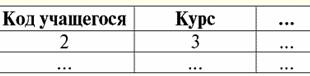
So what do we see? Firstly, each of the basic relations (or from entity classes, which is the same) "Schoolchildren", "Students" and "Postgraduate students" corresponds to its own attributes, such as "Class", "Course" and "Year of study" . Each of these attributes characterizes members of its own entity class. We also see that the primary key of the parent entity class "Students" migrates to each child entity class and forms the primary foreign key there. With the help of these connections, we can determine by the code of any student his first name, last name and patronymic, information about which we will not find in the corresponding child entity classes themselves. Secondly, since we are talking about a fully identifying (or categorical) relationship of entity classes, we will pay attention to the multiplicity of relationships between the parent entity class and its child classes. The parent end of each of these links has a multiplicity of "one", and each child end of the links has a multiplicity of "at most one". If we recall the definition of a fully identifying relationship of entity classes, it becomes clear that a really unique student code, which is the primary key of the "Students" entity class, specifies at most one attribute with such a code in each child entity class "Student", "Students". and Postgraduates. Therefore, all bonds have just such multiplicities. Let's write a fragment of operators for creating basic relations "Schoolchildren" and "Students" with the definition of rules for maintaining referential integrity of the cascade type. So we have: Create table Pupils ... primary key (Student code) foreign key (Student ID) references Students (Student ID) on update cascade on delete cascade Create table Students ... primary key (Student code) foreign key (Student ID) references Students (Student ID) on update cascade on delete cascade; Thus, we see that in the child entity class (or relationship) "Student" the primary foreign key is set, referring to the parent entity class (or relationship) "Students". The cascade rule for maintaining referential integrity determines that when attributes of the parent entity class "Students" are deleted or updated, the corresponding attributes of the child relation "Student" will be automatically (cascaded) updated or deleted. Similarly, when attributes of the parent entity class "Students" are deleted or updated, the corresponding attributes of the child relation "Students" will also be automatically updated or deleted. It should be noted that it is this referential integrity rule that is used here, because in this context (the list of students) it is not rational to prohibit the deletion and updating of information, and also to assign an undefined value instead of real information. Now let's give an example of the entity classes described in the previous diagram, only presented in tabular form. So, we have the following relationship tables: Pupils - parent relationship that combines information about the attributes of all other relationships:
Pupils - child relation:
Students - second child relation:
PhD students - third child relation:
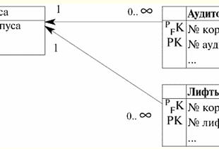
So, indeed, we see that the child classes of entities do not contain information about the last name, first name and patronymic of students, i.e. schoolchildren, students and graduate students. This information can only be obtained through references to the parent entity class. We also see that different student codes in the "Students" entity class can correspond to different child entity classes. So, about the student with the code "1" Nikolai Zabotin, nothing is known in the parental relationship, except for his name, and all other information (who he is, a schoolboy, student or graduate student) can only be found by contacting the corresponding child entity class (determined by the code). Similarly, you need to work with the rest of the students, whose codes are specified in the parent entity class "Students". 5. Composition The relationship of entity classes of the composition type, like the two previous ones, does not belong to the type of recursive relationship. Composition (or, as it is sometimes called, composite aggregation) is a relationship of one parent entity class with multiple child entity classes, just like the relationship we discussed above. Generalization. But if generalization was defined as a relationship of entity classes described by fully identifying relationships, then composition, in turn, is described by incompletely identifying relationships, i.e. during composition, each attribute of the primary key of the parent entity class migrates to the key attribute of the child entity class. And at the same time, the migrating key attributes only partially form the primary key of the child entity class. So, with composite aggregation (with composition), the parent entity class (or unit) is associated with multiple child entity classes (or components). In this case, the components of the aggregate (i.e., the components of the parent entity class) refer to the aggregate through a foreign key that is part of the primary key and, therefore, cannot exist outside the aggregate. In general, composite aggregation is an enhanced form of simple aggregation (which we will talk about a little later). A composition (or composite aggregation) is characterized by the fact that: 1) the reference to the assembly is involved in the identification of the components; 2) these components cannot exist outside the aggregate. An aggregation (a relationship that we will consider further) with necessarily non-identifying relationships also does not allow components to exist outside the aggregate and is therefore close in meaning to the implementation of composite aggregation described above. Let's build a key diagram that describes the relationship between one parent entity class and several child entity classes, i.e., describing the relationship of entity classes of the composite aggregation type. Let this be a key diagram depicting the composition of buildings of a certain campus, including buildings, their classrooms and elevators. So this diagram will look like this:
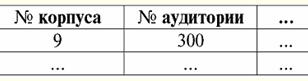
So let's take a look at the diagram we just created. What do we see in it? First, we see that the relationship used in this composite aggregation is indeed identifying and indeed not fully identifying. After all, the primary key of the parent entity class "Buildings" is involved in the formation of the primary key of the child entity classes "Audiences" and "Elevators", but does not completely define it. The primary key "Case No" of the parent entity class migrates to the foreign primary keys "Case No" of both child classes, but, in addition to this migrated key, both child entity classes also have their own primary key, respectively "Audience No" and "Elevator No. ", i.e. the composite primary keys of the child entity classes are only partially formed attributes of the primary key of the parent entity class. Now let's look at the multiplicities of links connecting the parent and both child classes. Since we are dealing with incompletely identifying links, the multiplicities are present: "one" and "many". The multiplicity "one" is present at the parent end of both relationships and symbolizes that in the list of all available corpora (and the entity class "Corpus" is just such a list), each number can occur only once, (and no more than that) times. And, in turn, among the attributes of the "Audience" and "Elevators" classes, each building number can occur many times, since there are more audiences (or elevators) than buildings, and in each building there are several auditoriums and elevators. Thus, when listing all classrooms and elevators, we will inevitably repeat the building numbers. And, finally, as in the case of the previous type of relationship, let's write down the fragments of the operators for creating basic relations (or, which is the same thing, entity classes) "Audiences" and "Elevators", and we will do this with the definition of rules for maintaining referential integrity of the cascade type. So this statement would look like this: Create table Audiences ... primary key (corpus number, audience number) foreign key (case number) references Patterns (case number) on update cascade on delete cascade Create table Lifts ... primary key (case number, elevator number) foreign key (case number) references Patterns (case number) on update cascade on delete cascade; Thus, we have set all the necessary primary and foreign keys of the child entity classes. We again took the rule of maintaining referential integrity as cascade, since we have already described it as the most rational. Now we will give an example in tabular form of all the entity classes we have just considered. Let us describe those basic relationships that we have reflected with the help of a diagram in the form of tables, and for clarity, we will introduce a certain amount of indicative data there. Shells The parent relationship looks like this:
Audience - child entity class:
Elevators - the second child entity class of the parent class "Enclosures":
So, we can see how information is organized for all buildings, their classrooms and elevators in this database, which can be used by any real-life educational institution. 6. Aggregation Aggregation is the last type of relationship between entity classes that will be considered as part of our course. It is also not recursive, and one of its two types is quite close in meaning to the previously considered composite aggregation. So, aggregation is the relationship of one parent entity class with multiple child entity classes. In this case, the relationship can be described by two types of relationships: 1) necessarily non-identifying links; 2) optional non-identifying links. Recall that with necessarily non-identifying relationships, some attributes of the primary key of the parent entity class are transferred to a non-key attribute of the child class, and Null values for all attributes of the migrating key are prohibited. And with not necessarily non-identifying relationships, the migration of primary keys occurs according to exactly the same principle, but Null-values for some attributes of the migrating key are allowed. When aggregating, the parent entity class (or unit) is associated with multiple child entity classes (or components). The components of the aggregate (i.e., the parent entity class) refer to the aggregate through a foreign key that is not part of the primary key, and therefore, in the case not necessarily non-identifying links, aggregate components can exist outside of the aggregate. In the case of aggregation with necessarily non-identifying relationships, the components of the aggregate are not allowed to exist outside the aggregate, and in this sense, aggregation with necessarily non-identifying relationships is close to composite aggregation. Now that it has become clear what an aggregation type relationship is, let's build a key diagram that describes the operation of this relationship. Let our future diagram describe the marked components of cars (namely the engine and chassis). At the same time, we will assume that the decommissioning of the car implies the decommissioning of the chassis along with it, but does not imply the simultaneous decommissioning of the engine. So our key diagram looks like this:
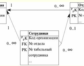
So what do we see in this key diagram? First, the relationship of the parent entity class "Cars" with the child entity class "Motors" is not necessarily non-identifying, because the "Car #" attribute allows Null values among its values. In turn, this attribute allows Null-values for the reason that decommissioning of the engine, by condition, does not depend on the decommissioning of the entire vehicle and, therefore, when decommissioning a car, it does not necessarily occur. We also see that the "Engine #" primary key of the "Cars" entity class migrates to the non-key attribute "Engine #" of the "Engines" entity class. And at the same time, this attribute acquires the status of a foreign key. And the primary key in this Engines entity class is the Engine Marker attribute, which does not refer to any attribute of the parent relationship. Secondly, the relationship between the parent entity class "Motors" and the child entity class "Chassis" is necessarily a non-identifying relationship, because the foreign key attribute "Car #" does not allow Null values among its values. This, in turn, occurs because it is known by the condition that the decommissioning of the car implies the mandatory simultaneous decommissioning of the chassis. Here, just as in the case of the previous relationship, the primary key of the parent entity class "Motors" migrates to the non-key attribute "Car number" of the child entity class "Chassis". At the same time, the primary key of this entity class is the "Chassis Marker" attribute, which does not refer to any attribute of the "Motors" parent relationship. Move on. For the best assimilation of the topic, let's write down again the fragments of the operators for creating the basic relations "Motors" and "Chassis" with the definition of rules for maintaining referential integrity. Create table Engines ... primary key (Motor marker) foreign key (vehicle no.) references Cars (vehicle no.) on update cascade on delete set Null Create table Chassis ... primary key (chassis marker) foreign key (vehicle no.) references Cars (vehicle no.) on update cascade on delete cascade; We see that we used the same rule for maintaining referential integrity everywhere - cascade, since even earlier we recognized it as the most rational of all. However, this time we used (in addition to the cascade rule) the set Null referential integrity rule. Moreover, we used it under the following condition: if some value of the primary key "Car number" from the parent entity class "Cars" is deleted, then the value of the foreign key "Car number" of the child relation "Engines" referring to it will be assigned a Null-value . 7. Unification of attributes If, during the migration of primary keys of a certain parent entity class, attributes from different parent classes that coincide in meaning get into the same child class, then these attributes must be "merged", i.e., it is necessary to carry out the so-called unification of attributes. For example, in the case when an employee can work in an organization, being listed in no more than one department, after unifying the "Organization Code" attribute, we get the following key diagram:
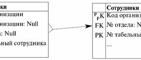
When migrating the primary key from the parent entity classes "Organization" and "Departments" to the child class "Employees", the attribute "Organization ID" falls into the entity class "Employees". And twice: 1) first time with marker PFK from the entity class "Organization" when establishing an incompletely identifying relationship; 2) and the second time, with the FK marker with the condition of accepting Null-values from the "Departments" entity class when establishing a not necessarily non-identifying relationship. When unified, the "Organization ID" attribute takes on the status of a primary/foreign key attribute, absorbing the status of the foreign key attribute. Let's build a new key diagram that demonstrates the unification process itself:
Thus, the unification of attributes took place. << Back: Database Schema Design (Different types and multiplicities of connections. Diagrams. Types of diagrams. Relationships and key migration) >> Forward: Expert systems and production model of knowledge (Purpose of expert systems. Structure of expert systems. Participants in the development of expert systems. Modes of operation of expert systems. Product model of knowledge)
The existence of an entropy rule for quantum entanglement has been proven
09.05.2024 Mini air conditioner Sony Reon Pocket 5
09.05.2024 Energy from space for Starship
08.05.2024
▪ High Voltage 800W Laboratory Power Supplies TDK-Lambda ▪ Drops of primary matter of the Universe are created ▪ Drivers for switching white LEDs EL7513 ▪ Metal foam - thermal insulator ▪ Silicone wristbands measure air quality
▪ section of the site History of technology, technology, objects around us. Article selection ▪ article by Thomas Gray. Famous aphorisms ▪ article Why Guy de Maupassant did not like the Eiffel Tower, but always dined there? Detailed answer ▪ article Field bug. Legends, cultivation, methods of application ▪ article Coordinating devices. Encyclopedia of radio electronics and electrical engineering
Home page | Library | Articles | Website map | Site Reviews
www.diagram.com.ua |


 See other articles Section