|
|


 Arabic
 Bengali
 Chinese
 English
 French
 German
 Hebrew
 Hindi
Hindi Italian
 Japanese
 Korean
 Malay
Malay Polish
 Portuguese
 Spanish
 Turkish
 Ukrainian
 Vietnamese
|
Lecture notes, cheat sheets
Database. Database Schema Design (Most Important)
Directory / Lecture notes, cheat sheets Table of contents (expand) Lecture No. 11. Designing database schemas The most common means of abstracting database schemas when designing at the logical level is the so-called entity-relationship model. It is also sometimes called ER model, where ER is an abbreviation of the English phrase Entity - Relationship, which literally translates as "entity - relationship". The elements of such models are entity classes, their attributes and relationships. We give explanations and definitions of each of these elements. Entity class is like a methodless class of objects in the sense of object-oriented programming. When moving to the physical layer, entity classes are converted into basic relational database relationships for specific database management systems. They, like the basic relations themselves, have their own attributes. Let us give a more precise and rigorous definition of the objects just given. class is called a named description of a collection of objects with common attributes, operations, relationships and semantics. Graphically, a class is usually depicted as a rectangle. Each class must have a name (a text string) that uniquely distinguishes it from all other classes. class attribute is a named property of a class that describes the set of values that instances of this property can take. A class can have any number of attributes (in particular, it can have no attributes). A property expressed by an attribute is a property of the modeled entity that is common to all objects of the given class. So an attribute is an abstraction of the state of an object. Any attribute of any class object must have some value. The so-called relationships are implemented using the declaration of foreign keys (we have already met similar phenomena before), i.e., in relation, foreign keys are declared that refer to the primary or candidate keys of some other relationship. And through this, several different independent basic relations are "linked" into a single system called a database. Further, the diagram that forms the graphical basis of the entity-relationship model is depicted using the unified modeling language UML. A great many books are devoted to the object-oriented modeling language UML (or Unified Modeling Language), many of which have been translated into Russian (and some written by Russian authors). In general, UML allows you to model different types of systems: purely software, purely hardware, software-hardware, mixed, explicitly including human activities, etc. But, among other things, as we have already mentioned, the UML language is actively used to design relational databases. For this, a small part of the language (class diagrams) is used, and even then not in full. From a relational database design perspective, modeling capabilities are not too different from those of ER diagrams. We also wanted to show that in the context of relational database design, structural design methods based on the use of ER diagrams and object-oriented methods based on the use of the UML language differ mainly only in terminology. The ER model is conceptually simpler than UML, it has fewer concepts, terms, and application options. And this is understandable, since different versions of ER models were developed specifically to support relational database design, and ER models contain almost no features that go beyond the real needs of a relational database designer. The UML belongs to the object world. This world is much more complicated (if you like, more incomprehensible, more confusing) than the relational world. Because the UML can be used for unified object-oriented modeling of anything, the language contains a plethora of different concepts, terms, and use cases that are redundant from a relational database design perspective. If we extract from the general mechanism of class diagrams what is really required for designing relational databases, then we will get exactly ER diagrams with a different notation and terminology. It is curious that when forming class names in the UML, the use of an arbitrary combination of letters, numbers, and even punctuation marks is allowed. However, in practice, it is recommended to use short and meaningful adjectives and nouns as class names, each of which begins with a capital letter. (We will consider the concept of a diagram in more detail in the next paragraph of our lecture.) 1. Various types and multiplicities of bonds The relationship between relationships in the design of database schemas is depicted as lines connecting entity classes. Moreover, each of the ends of the connection can (and generally should) be characterized by the name (ie, the type of connection) and the multiplicity of the role of the class in the connection. Let us consider in more detail the concepts of multiplicity and types of connections. multiplicity (multiplicity) is a characteristic that indicates how many attributes of an entity class with a given role can or should participate in each instance of a relationship of some kind. The most common way to specify the cardinality of a relationship role is to directly specify a specific number or range. For example, specifying "1" says that each class with a given role must participate in some instance of this connection, and exactly one object of the class with this role can participate in each instance of the connection. Specifying the range "0..1" indicates that not all objects of the class with a given role are required to participate in any instance of this relationship, but only one object can participate in each instance of the relationship. Let's talk about multiplicity in more detail. Typical, most common cardinalities in database design systems are the following cardinalities: 1) 1 - the multiplicity of the connection at its corresponding end is equal to one; 2) 0... 1 - this form of notation means that the multiplicity of a given connection at its corresponding end cannot exceed one; 3) 0... ∞ - this multiplicity is simply deciphered as “many”. It is curious that, as a rule, “a lot” means “nothing”; 4) 1... ∞ - this designation was given to the multiplicity “one or more”. Let us give an example of a simple diagram to illustrate the work with different multiplicities of links.
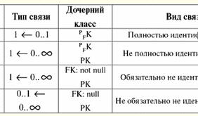
According to this diagram, one can easily understand that each ticket office has many tickets, and, in turn, each ticket is located in one (and no more than that) ticket office. Now consider the most common types or names of links. Let's list them: 1) 1: 1 - this designation was given to the connection "one to one", i.e., it is, as it were, a one-to-one correspondence of two sets; 2) 1 : 0... ∞ - this is a designation for a connection like "one to many". For brevity, such a relationship is called "1: M". In the diagram considered earlier, as you can see, there is a relationship with just such a name; 3) 0... ∞ : 1 - this is a reversal of the previous connection or a connection of the type "many to one"; 4) 0... ∞ : 0... ∞ is a designation for a connection like "many to many", i.e. there are many attributes at each end of the link; 5) 0... 1 : 0... 1 - this is a connection similar to the previously introduced “one to one” type connection, it, in turn, is called "no more than one to no more than one"; 6) 0... 1 : 0... ∞ - this is a connection similar to a one-to-many connection, it is called “no more than one to many”; 7) 0... ∞ : 0... 1 - this is a connection, in turn, similar to a many-to-one type connection, it is called "many to no more than one". As you can see, the last three connections were obtained from the connections that are listed in our lecture under the numbers one, two and three by replacing the multiplicity of "one" with the multiplicity of "no more than one". 2. Diagrams. Types of charts And now let's finally proceed directly to the consideration of diagrams and their types. In general, there are three levels of the logical model. These levels differ in the depth of representation of information about the data structure. These levels correspond to the following diagrams: 1) presentation diagram; 2) key diagram; 3) complete attribute diagram. Let us analyze each of these types of diagrams and explain in detail the meaning of their differences in the depth of presentation of information about the data structure. 1. Presentation diagram. Such diagrams describe only the most basic classes of entities and their relationships. The keys in such diagrams may not be described at all, and, accordingly, the connections may not be individualized in any way. Therefore, many-to-many relationships are acceptable, although they are usually avoided or, if they do exist, fine-tuned. Composite and multi-valued attributes are also perfectly valid, although we wrote earlier that basic relations with such attributes are not reduced to any normal form. Interestingly, of the three types of diagrams we have considered, only the last type (full attribute diagram) assumes that the data presented with it is in some normal form. Whereas the presentation diagram already considered and the key diagram next in line do not imply anything of the kind. Such diagrams are usually used for presentations (hence their name - presentational, that is, used for presentations, demonstrations, where excessive detail is not needed). Sometimes when designing databases, it is necessary to consult with experts in the subject area that this particular database deals with information. Then presentation diagrams are also used, because in order to obtain the necessary information from specialists in a profession far from programming, excessive clarification of specific details is not required at all. 2. Key diagram. Unlike presentation diagrams, key diagrams necessarily describe all classes of entities and their relationships, however, in terms of only primary keys. Here, many-to-many relationships are already necessarily detailed (i.e., relationships of this type in their pure form simply cannot be specified here). Multivalued attributes are still allowed in the same way as in the presentation diagram, but if they are present in the key diagram, they are usually converted to independent entity classes. But, curiously, single-valued attributes may still be incompletely represented or described as composite. These "liberties", which are still valid in such diagrams as presentational and key diagrams, are not allowed in the next type of diagram, because they determine that the base relation is not normalized. Thus, we can conclude that key diagrams in the future assume only "hanging" attributes on already described entity classes, i.e., using a presentation diagram, it is enough to describe the most necessary entity classes, and then, using a key diagram, add everything to it necessary attributes and specify all the most important links. 3. Full attribute diagram. Complete attribute diagrams describe in the most detail of all the above all classes of entities, their attributes and relationships between these entity classes. As a rule, such charts represent data that is in the third normal form, so it is natural that in the basic relations described by such charts, the presence of compound or multivalued attributes is not allowed, just as the presence of non-granular many-to-many relationships is not allowed. However, complete attribute charts still have a drawback, that is, they cannot be fully called the most complete of the charts in terms of data presentation. For example, the peculiarity of specific database management systems when using full attribute diagrams is still not taken into account, and in particular, the data type is specified only to the extent necessary for the required logical level of modeling. 3. Associations and key migration A little earlier, we already talked about what relationships are in databases. In particular, the relationship was established when declaring the foreign keys of the relationship. But in this section of our course, we are no longer talking about basic relations, but about cash registers of entities. In this sense, the process of establishing relationships is still associated with the declarations of various keys, but now we are talking about the keys of entity classes. Namely, the process of establishing relationships is associated with the transfer of a simple or composite primary key of one entity class to another class. The process of such transfer is also called key migration. In this case, the entity class whose primary keys are transferred is called parent class, and the class of entities into which foreign keys are migrated is called child class entities. In a child entity class, key attributes receive the status of foreign key attributes and may or may not participate in the formation of its own primary key. Thus, when a primary key is migrated from a parent to a child entity class, a foreign key appears in the child class that refers to the primary key of the parent class. For the convenience of the formulaic representation of key migration, we introduce the following key markers: 1) PK - this is how we will denote any attribute of the primary key (primary key); 2) FK - with this marker we will denote the attributes of a foreign key (foreign key); 3) PFK - with such a marker we will denote an attribute of the primary / foreign key, i.e. any such attribute that is part of the only primary key of some entity class and at the same time is part of some foreign key of the same entity class. Thus, attributes of an entity class with PK and FK markers form the primary key of this class. And attributes with FK markers and PFK are part of some foreign keys of this entity class. In general, keys can migrate in different ways, and in each such different case, some kind of connection arises. So, let's consider what types of links exist depending on the key migration scheme. In total, there are two key migration schemes. 1. Migration scheme ∀PK (PK |→PFK); In this entry, the symbol "|→" means the concept of "migrates", i.e. the above formula will be read as follows: any (each) attribute of the primary key PK of the parent entity class is transferred (migrates) to the primary key PFK child entity class, which, of course, is also a foreign key for this class. In this case, we are talking about the fact that, without exception, every key attribute of the parent entity class must be migrated to the child entity class. This type of connection is called identifying, since the key of the parent entity class is entirely involved in the identification of child entities. Among the links of the identifying type, in turn, there are two more possible independent types of links. So, there are two types of identifying links: 1) fully identifying. An identifying relationship is said to be fully identifying if and only if the attributes of the migrating primary key of the parent entity class completely form the primary (and foreign) key of the child entity class. A fully identifying relationship is also sometimes called categorical, because a fully identifying relationship identifies child entities across all categories; 2) not fully identifying. An identifying relationship is said to be incompletely identifying if and only if the attributes of the migrating primary key of the parent entity class only partially form the primary (and at the same time foreign) key of the child entity class. Thus, in addition to the key with the marker PFK will also have a key marked PK. In this case, the foreign key PFK of the child entity class will be completely determined by the primary key PK of the parent entity class, but simply the primary key PK of this child relationship will not be determined by the primary key PK of the parent entity class, it will be by itself. 2. Scheme of migration ∃PK (PK |→ FK); Such a migration scheme should be read as follows: there are such primary key attributes of the parent entity class that, during migration, are transferred to the mandatory non-key attributes of the child entity class. Thus, in this case, we are talking about the fact that some, and not all, as in the previous case, the primary key attributes of the parent entity class are transferred to the child entity class. In addition, if the previous migration scheme defined migration to the primary key of the child relation, which at the same time also became a foreign key, then the last type of migration determines that the primary key attributes of the parent entity class migrate to ordinary, initially non-key attributes, which after that acquire foreign key status. This type of connection is called non-identifying, because, indeed, the parent key is not entirely involved in the formation of child entities, it simply does not identify them. Among non-identifying relationships, two possible types of relationships are also distinguished. Thus, non-identifying relationships are of the following two types: 1) necessarily non-identifying. Non-identifying relationships are said to be necessarily non-identifying if and only if Null values for all migrating key attributes of a child entity class are prohibited; 2) optionally non-identifying. Non-identifying relationships are said to be not necessarily non-identifying if and only if null values are allowed for some migrating key attributes of the child entity class. We summarize all of the above in the form of the following table in order to facilitate the task of systematizing and understanding the material presented. Also in this table we will include information about which types of relationships ("no more than one to one", "many to one", "many to no more than one") correspond to which types of relationships (fully identifying, not fully identifying, necessarily not identifying, not necessarily non-identifying). So, between the parent and child entity classes, the following type of relationship is established, depending on the type of relationship.
So, we see that in all cases except the last one, the reference is not empty (not null) → 1. Note the trend that at the parent end of the connection in all cases except the last one, the multiplicity is set to "one". This is because the value of the foreign key in the cases of these relationships (namely, fully identifying, not fully identifying, and necessarily not identifying types of relationships) must necessarily correspond (and, moreover, the only) value of the primary key of the parent entity class. And in the latter case, due to the fact that the value of the foreign key can be equal to the Null value (the FK: null validity flag), the multiplicity is set to "no more than one" at the parent end of the relationship. We carry out our analysis further. At the child end of the connection, in all cases, except for the first, the multiplicity is set to "many". This is because, due to incomplete identification, as in the second case, (or no such identification at all, in the second and third cases), the value of the primary key of the parent entity class can repeatedly occur among the values of the foreign key of the child class. And in the first case, the relationship is fully identifying, so the attributes of the primary key of the parent entity class can only occur once among the attributes of the keys of the child entity class. << Back: Normal forms (The meaning of normalizing database schemas. First normal form (1NF). Second normal form (2NF). Third normal form (3NF). Boyce-Codd normal form (NFBC). Nesting of normal forms) >> Forward: Entity class relationships (Hierarchical recursive communication. Network recursive communication. Association. Generalizations. Composition. Aggregation. Attribute unification)
▪ Legal psychology. Lecture notes ▪ Theory of Government and Rights. Lecture notes ▪ Hospital Pediatrics. Lecture notes
The existence of an entropy rule for quantum entanglement has been proven
09.05.2024 Mini air conditioner Sony Reon Pocket 5
09.05.2024 Energy from space for Starship
08.05.2024
▪ Organic CMOS image sensor with electronic sensitivity control in NIR ▪ Spinach as fuel for electric cars ▪ Turning ordinary material into a magnet
▪ site section Parameters, analogues, marking of radio components. Article selection ▪ article Standard jumps. Popular expression ▪ article What is caffeine? Detailed answer ▪ article When there is no zener diode. Encyclopedia of radio electronics and electrical engineering
Home page | Library | Articles | Website map | Site Reviews
www.diagram.com.ua |


 See other articles Section