|
|


 Arabic
 Bengali
 Chinese
 English
 French
 German
 Hebrew
 Hindi
Hindi Italian
 Japanese
 Korean
 Malay
Malay Polish
 Portuguese
 Spanish
 Turkish
 Ukrainian
 Vietnamese
|
ENCYCLOPEDIA OF RADIO ELECTRONICS AND ELECTRICAL ENGINEERING matching devices. Encyclopedia of radio electronics and electrical engineering
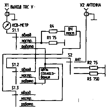
Encyclopedia of radio electronics and electrical engineering / Knots of amateur radio equipment. Filters and matching devices Even 10 ... 15 years ago, there was practically no problem with the use of matching devices (CS), respectively, there were almost no descriptions of such devices in amateur radio literature. The point, probably, is that earlier in the USSR, almost everyone used home-made lamp equipment, the output stage of which could be matched with almost anything. Transistor RAs produce much more harmonics than tube ones. And often a low-quality P-circuit at the output of a transistor RA cannot cope with their filtering. In addition, it must be taken into account that the number of TV channels has increased many times over compared to what it was a few years ago! The purpose of the matching device The control system provides the transformation of the output impedance of the transmitter into the impedance of the antenna. It is irrational to use a control system with a tube power amplifier having a P-loop with all three smoothly tunable elements, since the P-loop provides matching in a wide range of output impedances. Only in cases where the elements of the P-loop exclude adjustment, the use of SU is beneficial. In any case, the SU noticeably reduces the level of harmonics, and its use as a filter is fully justified. With good tuned resonant antennas and good PA, there is no need to use a matching device. But when the antenna alone operates on several bands, and the RA does not always give out what is needed, the use of the SU gives good results. Principles of building a matching device The classical SU has the form shown in Fig. 1. As you can see, it consists of a matching circuit (CS), which is made according to one of the well-known schemes (the CS itself is often called "matching device", "ATU"), an SWR meter, an RF bridge showing the degree of antenna mismatch, an equivalent antenna R 1, and control loads R2, R3. Without all this "environment" SU is only a chain of coordination, nothing more.
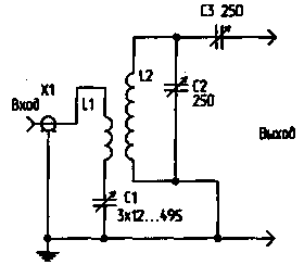
Let's analyze the principle of operation of the device. In the S 1 "Bypass" position, the transmitter output is connected to S2, which makes it possible either to directly connect the antenna, or to turn on one of the load equivalents (R2 or R3) to the output and check the possibility of matching the transmitter with it. In the "Setting" position, the transmitter operates on a matched load. Also, through the resistance R4, the RF bridge is turned on. According to the balance of this bridge, the matching circuit is used to tune the antenna. Resistors R2 and R3 make it possible to check whether it is possible to tune the matching circuit to them. Having configured the CA, turn on the "Work" mode. In this mode, the matching circuit is adjusted a little more to the minimum of the SWR meter readings. Below we consider the main CAs used in practice. Matching circuit on a parallel circuit One of the most efficient and simple CAs is shown in Figure 2. The transmitter is connected via coil L1 and capacitor C1. L1 is from a quarter to a sixth of the number of turns of L2 and is wound in its lower part. L1 must be separated from L2 by good insulation.
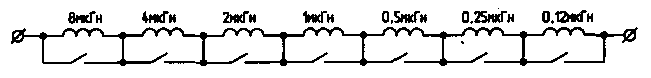
In this scheme, the transmitter is connected to the CS only by magnetic flux, and here the issue of lightning protection of the output stage is automatically resolved. Capacitor C1 for operation at 1,8 MHz. should have a maximum capacitance - 1500 pF, and for operation at 28 MHz - 500 pF. C2 and C1 should have the largest possible gap between the plates. The load resistance range is from 10 ohms to several kilo ohms. High efficiency operation is provided in two adjacent bands, such as 1,8 and 3,5 MHz. For efficient operation in several ranges, it is necessary to switch L1 and L2. At low powers (up to 100 W), it is most efficient and easy to make a set of replacement coils and install them using base panels from old radio tubes. Any experiments related to connecting L1 and L2 coils in parallel to reduce their inductance for operation on the HF bands, connecting these coils to the taps, the "cunning" parallel connection of the coils significantly reduce the efficiency of this DC at HF. The coil data for the circuit in Fig. 2 are shown in Table 1. Table 1
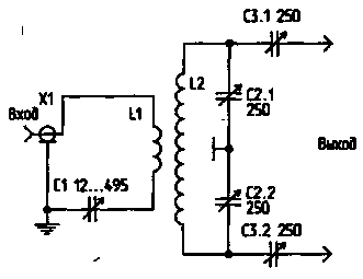
Although symmetrical antennas are rarely used at present, it is worth considering the possibility of operating this DS on a symmetrical load (Fig. 3).
Its only difference from the circuit in Fig. 2 is that the voltage for the load is removed symmetrically. L1 must be located symmetrically with respect to L2. Capacitors C1 and C2 must be on the same axis. It is necessary to take measures to reduce the influence of the capacitive effect on L2, i.e. it should be far enough from the metal walls. The L2 data for the circuit in Fig. 3 are given in Table 2. Table 2
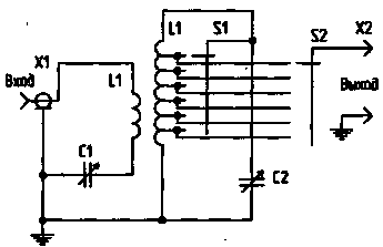
There are also constructions of a simplified version of this CA.
Figure 4 shows an asymmetric circuit, Figure 5 shows a symmetrical circuit. But, unfortunately, as experience shows, these circuits cannot give such careful coordination as in the case of using capacitors C3 (Fig. 2) or C3.1, C3.2 (Fig. 3).
Particular care must be taken in the construction of multi-band DS operating on this principle (Fig. 6). Due to the decrease in the Q-factor of the coil and the large capacity of the ground taps, the efficiency of such a system in the HF bands is low, but the use of such a system in the 1,8 ... 7 MHz bands is quite acceptable.
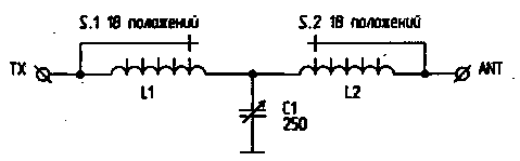
Setting up the CA shown in Figure 2 is simple. Capacitor C1 is set to the maximum position, C2 and C3 to the minimum, then with the help of C2 the circuit is tuned to resonance, and then, increasing the connection with the antenna using C3, they achieve maximum power output to the antenna, while constantly adjusting C2 and, according to opportunities, C1. You should strive to ensure that after setting up the C3 CA has the maximum capacity. T-chain matching This scheme (Fig. 7) is widely used when working with asymmetric antennas.
For the normal operation of this DC, a smooth adjustment of the inductance is necessary. Sometimes even half a turn is critical to matching. This limits the use of tapped inductors or requires individual selection of the number of turns for a particular antenna. It is necessary that the capacitance of C1 and C2 to the "ground" be no more than 25 pF, otherwise the efficiency may decrease by 24 ... 28 MHz. It is necessary that the "cold" end of the L1 coil be carefully grounded. This DC has good parameters: efficiency - up to 80% with the transformation of 75 ohms to 750 ohms, the ability to match the load from 10 ohms to several kilo-ohms. With only one variable inductance of 30 μH, you can cover the entire range from 3,5 to 30 MHz, and by connecting in parallel C1, C2 constant capacitors of 200 pF, you can work at 1,8 MHz. Unfortunately, variable inductance is expensive and difficult to construct. W3TS proposed a switchable "digital inductor" (Figure 8). Using such an inductance, with the help of switches, you can visually set its desired value.
Another attempt to simplify the design was made by AEA by making a matching device according to the scheme shown in Fig. 9. Indeed, the circuits in Fig. 7 and Fig. 9 are equivalent. But structurally it is much easier to use one grounded high-quality capacitor instead of two isolated ones, and replace the expensive variable inductance with cheap permanent inductors with taps. This DS worked well from 1,8 to 30 MHz, transforming 75 ohms to 750 ohms and 15 ohms. But when working with real antennas, the discreteness of inductance switching sometimes affected. In the presence of 18, and preferably 22 position switches, this CA can be recommended for practical implementation. In this case, it is necessary to reduce the length of the coil leads to the switch to a minimum. Switches for 11 AEA AT-30 TUNER L1-L2-25 Turns, diam. coils 45 mm winding pitch 4 mm taps from each turn along the length of 10 turns, then after 2 turns of positions make it possible to make a CS only for working on part of the amateur bands - from 1,8 to 7 or from 10 to 28 MHz.
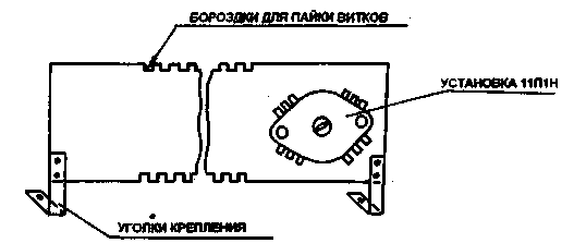
The coil is structurally convenient to perform as shown in Fig. 10. Its frame is a bar of double-sided fiberglass with cuts for coil turns. A switch is installed on this bar (for example, 11P1N). The taps from the coil go to the switch on both sides of the fiberglass strip.
When working with symmetrical antennas, together with a T-shaped matching device, a balancing transformer 1:4 or 1:6 is used at the output of the DS. Such a decision cannot be considered effective, because. many balanced antennas have a large reactive component, and ferrite transformers work very poorly with reactive loads. In this case, it is necessary to apply measures to compensate for the reactive component or use a DS (Fig. 3). U-shaped matching scheme U-shaped CS (or P-loop), the scheme of which is given in fig. 11 is widely used in amateur radio practice.
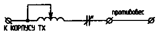
In real conditions, when the transmitter output is 50 ... 75 Ohm, and matching must be done in a wide range of load resistances, the parameters of the P-loop change tenfold. For example, at 3,5 MHz with Rin \u75d Rn \u1d 2 Ohm, the inductance L1 is approximately 2 μH, and C2000, C75 - 1 pF each, and with Rin \u20d 1 Ohm and RH a few kiloohms, the inductance L2000 is approximately 2 μH, the capacitance CXNUMX is about XNUMX pF, and CXNUMX is tens of picofarads. Such large variations in the values of the elements used limit the use of the P-loop as a CS. It is desirable to use a variable inductance. Capacitor Cl may have a small gap, and C2 should have a gap of at least 2 mm for every 200 watts of power. Improving the efficiency of the matching device To increase the efficiency of the transmitter, especially when using random antennas, a device called "artificial earth" helps. This device is effective when using random antennas and with poor radio grounding. This device brings to a resonant state the grounding system of the radio station (in the simplest case, a piece of wire). Since the parameters of the ground are included in the parameters of the antenna system, improving the efficiency of the ground improves the performance of the antenna. Conclusion The matching device should be used no more than it is really needed. You should choose the type of SU that you need. For example, it makes no sense to manufacture a broadband device for operation in the range of 1,8 ... 30 MHz, if you really do not "build" antennas for 1 ... 2 ranges, or surrogate antennas are used on these ranges. Here it is much more efficient to perform its own separate SU for each range. But of course, if you are using a transceiver with a non-adjustable output and most of your antennas are surrogate, then an all-band DC is needed here. All of the above applies to the "artificial earth" device.
Literature 1. Podgorny I. (EW1MM). HF ground/Ham radio HF and VHF. - 1995. - No. 9. Author: I. Grigorov (RK32ZK), Belgorod; Publication: N. Bolshakov, rf.atnn.ru
Air trap for insects
01.05.2024 The threat of space debris to the Earth's magnetic field
01.05.2024 Solidification of bulk substances
30.04.2024
▪ Ball lightning - maybe it's just an illusion ▪ Recharging through the asphalt ▪ Mini power station for charging gadgets ▪ TV Philips 55PUS9109 on Android
▪ site section Low frequency amplifiers. Article selection ▪ article Electric terminal from a tube. Tips for the home master ▪ article Who Discovered Australia? Detailed answer
Comments on the article: Vladimir Good article, useful for setting up a power amplifier. Vasya Thanks to the author
Home page | Library | Articles | Website map | Site Reviews
www.diagram.com.ua |


 Leave your comment on this article: