|
|


 Arabic
 Bengali
 Chinese
 English
 French
 German
 Hebrew
 Hindi
Hindi Italian
 Japanese
 Korean
 Malay
Malay Polish
 Portuguese
 Spanish
 Turkish
 Ukrainian
 Vietnamese
|
ENCYCLOPEDIA OF RADIO ELECTRONICS AND ELECTRICAL ENGINEERING Tubes or transistors? Lamps!. Encyclopedia of radio electronics and electrical engineering
Encyclopedia of radio electronics and electrical engineering / Tube Power Amplifiers What is "High-End"? It is unlikely that anyone will be able to answer this question unequivocally. The fact is that this concept is purely emotional. It is simply impossible to create an electroacoustic path that would satisfy absolutely everyone. One of the characteristic features of the new direction in the development of high-quality sound reproduction is the revival of interest in the use of electronic tubes in AF amplifiers. This is due to the fact that when conducting comparative listening to the sound of tube and transistor equipment, experts increasingly began to give preference to the first of them. In the article “Psychoacoustic criteria for sound quality and selection of UMZA parameters,” the author of these lines first tried to establish a connection between the objective characteristics of electronic tubes and the subjective perception of the sound provided by tube AF amplifiers. Let's look at this in more detail.
First of all, let us remind readers of the main features of using tubes in AF amplifiers. There are three known schemes for their connection: with a common cathode (Fig. 1, a), with a common anode (Fig. 1, b) and a common grid (Fig. 1, c). The four-terminal circuits U1 and U2 conventionally designate the input and output circuits of each of those shown in Fig. 1 cascades. Moreover, the four-terminal networks must be constructed in such a way that a direct current can flow through the anode circuits of the lamps, and the required constant bias voltage can be applied to the grid relative to the cathode. The most widely used amplifier stage is a circuit with a common cathode. In its simplest form it is shown in Fig. 2.
It is known that the properties of a lamp, as an element of an electrical circuit, are determined by the relationships between currents and voltages in the circuits of its electrodes. When calculating tube amplifiers, it is customary to use static anode-grid characteristics: ╡a = f(Uc) with Ua = const AND ╡a=f(Ua) with Uc=const. The families of these characteristics are interrelated, so having one of them, you can build others. Examples of such characteristics of a triode and pentode are shown in Fig. 3, respectively. 4 and XNUMX.
The main parameters of the lamp can be easily determined by static characteristics. The gain is defined as the ratio of the voltage increment at the anode to the voltage increment at the grid at a constant anode current: m = ΔUa /ΔUC at la=const. Internal resistance is defined as the ratio of the anode voltage increment to the anode current increment at a constant grid voltage: Ri= ∆Ua/∆la at Uc=const. The slope of the lamp is the ratio of the anode current increment to the grid voltage increment at a constant voltage at the anode: S = ΔIa/ΔUc at Ua= const. Now about the operation of tubes in a real amplifier stage. Conventionally, three modes are distinguished: A. B and C. In mode A, the initial position of the operating point is chosen such that, with a real signal amplitude, it moves within the linear section of the grid characteristic of the lamp. In mode B, the operating point is located at the lower bend of this characteristic, and in mode C - to the left of the bend. As a result, in the last two modes the lamp operates as a nonlinear element. The initial operating mode of the lamp is set by the voltages of the power supplies of the circuits of its electrodes minus the drops in constant voltages on the elements of these circuits. Voltage drops and currents in the electrode circuits can be easily found using the lamp characteristics. We will not dwell on the main features of the operation of a lamp in a linear amplifier stage and will not give the basic calculation formulas for one or another circuit for its inclusion; we will refer the reader to the literature [1, 2]. We only note that the properties of tube amplifier stages are essentially equivalent to the properties of similar stages on transistors. However, there are also differences. Firstly, the slope of the lamp does not depend on the temperature of the anode (within reasonable limits), but the current transfer coefficient of transistors h21e changes with fluctuations in the temperature of its crystal. As a result, in tube amplifiers it is possible to avoid infra-low-frequency modulation of the signal and ensure good reproduction of the low-frequency portion of the audio frequency spectrum. The existing misconception regarding “weak bass” in tube amplifiers is associated, in our opinion, with insufficient power of the output transformers and power transformers. Secondly, lamps. Unlike transistors, they are controlled by voltage, not current. This allows you to unload the previous stage in tube amplifiers and, accordingly, reduce the nonlinearity it introduces. We should not, of course, forget about the input capacitance of the subsequent stage, which can be quite high. Thus, in a cascade using a 6N2P lamp, its value at the maximum gain is about 73 pF. but to charge such a capacitance, a significantly lower current is required than the control current of the transistor stage. Thirdly, lamps are more individual than transistors in terms of the nonlinear distortions introduced into the signal. As an example, we give the levels of harmonic distortion of the output signal for two interchangeable lamps 12AX7 and 6N2P in equivalent stages (Table 1).
Similar information for transistor cascades was indicated in the author’s article, published in Radio No. 12, 1987. It should be borne in mind that changing the mode in both cases leads to a redistribution of the levels of harmonic components. Now let's talk about the factors influencing the sound quality provided by the output stages of vacuum tube amplifiers. Let's start with the power source, since, as practice shows, the operation of any amplification device largely depends on it. Due to the fact that installing a voltage stabilizer in a tube amplifier is uneconomical, the requirements for all elements of its power source increase. To eliminate losses in the network cable, its current load should not exceed 2,5 A/mm2 cross-section. Before the primary winding of the mains transformer, you need to install a suppression filter that suppresses high-frequency and impulse noise penetrating into the amplifier. True, it does not protect against the “clicks” that penetrate the amplifier when turning on and off household appliances with reactive loads (refrigerators, vacuum cleaners, etc.), but it protects against interference created by sources of powerful radio emissions. Special attention should be paid to the power transformer. Its design must ensure suppression of interference passing through the rejection filter. There are three main designs of transformers - armored, rod and toroidal. The most widely used armored transformers are those based on W-shaped magnetic cores. They are cheap, technologically advanced, but have large stray fields. In addition, with such transformers it is very difficult to eliminate interference and interference, and therefore suppress “clicks” when operating household appliances. Transformers based on toroidal magnetic cores do not have these disadvantages, but they are too expensive. The choice of the cross-section of the magnetic core of the network transformer and the location of its windings on it are very important. To improve sound quality, you need to strive to reduce the leakage inductance and the transformer’s own capacitance. Particular attention should be paid to insulation, shielding and the location of the network winding on the magnetic core. since any parasitic connections contribute to the penetration of interference from the network into the amplifier. When choosing the cross-section of the magnetic core and the diameter of the wires of the transformer windings, it is necessary to take into account that the current passing through the secondary winding loaded on the bridge rectifier can reach three times the rectified current. The practice of developing AF amplifiers shows that a real network transformer must have a two to three times margin in the cross-section of the steel of the magnetic core and the copper wire of the windings relative to generally accepted calculation methods. There are no special requirements for rectifiers of power supplies of tube power amplifiers that differ from the requirements for similar devices of transistor amplifiers. Is it possible that higher-voltage rectifier devices should be used for lamp ones, since the anode voltage of the lamps significantly exceeds the voltage required to power the transistors. Recently, however, it has become fashionable to use kenotrons in rectifiers instead of silicon diodes. Indeed, the kenotron opens more smoothly, and the current rectified by it contains fewer high-frequency components, however, good anti-aliasing filters and the correct installation topology make it possible to design an excellent rectifier using silicon diodes. In other words, with a properly made rectifier using silicon diodes, a kenotron rectifier has no advantages over it. The third main element of the amplifier's power supply is the anti-aliasing filter. In power supplies for high-quality AF amplifiers, it is advisable to use filters on fluoroplastic or polypropylene capacitors. However, such capacitors have a low specific capacitance and do not sufficiently smooth out the ripples of the rectified voltage. In this regard, it is necessary to install oxide capacitors in the filters. K50-27 are most suitable. Instead of one large-capacity capacitor, it is recommended to use several parallel-connected capacitors of smaller capacity and bypass the oxide capacitor with a small-capacity polypropylene capacitor. However, recently polypropylene capacitors K78-12 have appeared. K78-17 and K78-20 with a capacity of the order of tens of microfarads, designed for an operating voltage of 500 V. Now - about the factors that determine the dependence of the sound on the amplifier itself. When choosing a single-ended or push-pull power amplifier circuit, the following advantages and disadvantages are usually taken into account. The harmonics contained in the output signals of single-ended amplifiers are less noticeable to subjective perception; Such cascades provide a softer sound in the high-frequency register; they are simpler in circuitry and design. Among the disadvantages of single-ended cascades, low (15...20%) efficiency can be noted. as a consequence, low output power, high requirements for the level of ripple and stability of the power supply voltage, difficulties in reproducing lower audio frequencies. The last of these disadvantages is associated with the presence of constant magnetization of the magnetic circuit of the output transformer of a single-ended power amplifier. This leads to a decrease in the magnetic permeability of the magnetic core, and therefore to a decrease in the inductance of the primary winding of the output transformer and an increase in the cutoff frequency of its frequency response. Attempts to increase the inductance by increasing the number of turns of the primary winding yield little, since the bias increases and the real increase in inductance will be insignificant. In addition, as the winding resistance increases, the voltage lost across it will increase and the efficiency will decrease. The situation with the reproduction of lower sound frequencies can be improved by increasing the cross-section of the magnetic circuit, which is what many designers of single-ended tube amplifiers do. Push-pull power amplifiers reproduce lower audio frequencies better, since there is no permanent magnetization of the magnetic circuits in their output transformers. Such amplifiers have higher efficiency and output power, they are less demanding on the power supply parameters, and they require a simpler output transformer. However, push-pull amplifiers reproduce higher audio frequencies with less accuracy and have more complex circuitry. To obtain undistorted sound, the identical characteristics of the lamps of the push-pull output stage are very important. Usually they are selected according to the steepness and closing tension, but, as experience shows, selection based only on these parameters is not sufficient. Thus, when the currents of the output lamps are unbalanced, amplitude modulation of the harmonics of the output signal with a frequency of 100 Hz occurs. i.e., for example, when amplifying a signal with a frequency of 1000 Hz, components with a frequency of 900 and 1100 Hz will be present at the amplifier output. And this leads to the appearance of additional and, we dare to assure you, audible distortions. With imbalance, of course, the overall coefficient of nonlinear distortion also increases. Recent studies have shown that pairs of pumps must be selected according to their current-voltage characteristics with an accuracy of no worse than 5% over the entire range of operating currents. The issue of using OOS in a power amplifier can be decided taking into account the known advantages and disadvantages. Assuming that the advantages of OOS are well known to readers, we will only say that an amplifier without OOS, for example, reproduces higher and lower sound frequencies better and worse. Its characteristics strongly depend on the stability of the parameters of both the lamps and other circuit elements, as well as the properties of the power source. It requires more careful consideration of installation. The parameters of the amplifier's output stage are largely determined by the lamps operating in it. First of all. Taking into account the characteristics of the lamps, you should decide which of them is most appropriate to use in the amplifier - triodes or pentodes (tetrodes). For example, compared to pentodes, triodes provide better gain linearity and have lower internal resistance, but they have lower gain, and due to poorer utilization of the anode voltage, they do not allow for higher output power. As already noted, tubes are more individual in terms of the sound quality they provide. Let us present (Table 2) the spectrum of harmonics of the output signal of a single-ended power amplifier without OOS using an EL-34 lamp operating in mode A with an output signal amplitude corresponding to a power of 1 W. The level of the first harmonic is taken as XNUMX dB.
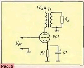
As can be seen from the table, amplifier stages on the same type of lamps, even from the same manufacturer, have different harmonic spectra of the output signal, which means that the sound they provide will be different. Selecting the operating mode of a power amplifier is usually not difficult. It is most advisable to use mode A, as it provides less distortion and better sound. It is much more difficult to solve the issue of the circuit design of the amplifier's output stage, but this will be discussed in the next article. Let's start our acquaintance with the circuitry of power amplifiers with a single-ended output stage operating in mode A. Its typical circuit is shown in Fig. 5. The cascade shown here is built on a triode, but it is permissible to use a tetrode or pentode.
To analyze the basic properties of a single-ended triode cascade, we will use the one shown in Fig. 6 family of idealized lamp anode characteristics. When the anode voltage is fully used, operating point B should be in the middle of the load line AB. The quiescent current is equal to Iao, the quiescent voltage is Uao. the amplitude of the sinusoidal voltage on the control grid is Umc, on the anode - Ima. The power supplied by the cascade to the load is P = 1/2(lma Uma), and the power consumed by it from the power source is Po = lao Uao. From here it is easy to find the efficiency of the cascade operating in mode A, No = P/Po = /2(lma Uma)/Ino Uno, and the power dissipated at the anode of the lamp, P = P0 - P_. Since in quiescent mode the power supplied by the lamp to the load is zero, the quiescent current of the cascade is chosen such that the power it consumes from the power source does not exceed the maximum permissible power dissipated at the anode of the lamp.
The functions of the anode load in the cascade we are considering are performed by the output transformer, and taking into account its efficiency, the power supplied directly to the loudspeaker head is Pn = ntrP_ If the initial power is Pn, then, using the same formula, we can determine the power that should in this case give the triode to the load: P_=Pn/mtP. In Fig. Figure 7 shows the dependences of the power P_ delivered to the load, known from the theory of amplification devices. Efficiency - No. and harmonic coefficient -Kg of the triode cascade from the ratio Rв/Ri. Analysis of these dependencies allows us to draw the following conclusions: - the triode amplifier stage delivers maximum power to the load with anode load resistance Ra=2Ri; - The efficiency of the cascade increases with increasing Rn/Rё approaching the value of 0,5; - an increase in the resistance of the anode load of the triode helps to reduce the nonlinear distortions introduced by the cascade.
Thus, in order to simultaneously obtain a large P_, a sufficiently high efficiency and low Kg, it is desirable to have a Ra/Ri ratio in the range of 2...4. If a tetrode or pentode is used in the output stage, the nature of these dependencies changes somewhat. It is known that the dependence of the triode anode current on the voltage on the anode and grid is described by the relation la=(Uc--Ua/m)3/2. which allows the designer, who has the anode characteristics of the lamp, to clearly select its operating mode. For the tetrode and pentode, such an equation did not exist until now. The authors of this article attempted to derive a similar formula for the 6P45S beam tetrode used by our company. As a result of the analysis, the relation Ia=1,8[1-1/(0.0012Ua2+ +1)](Uc/45+1)2 was obtained, which describes the behavior of this lamp, however, only at a voltage on its screen grid U3 equal to 175 V. For other voltages, instead of Uc, the expression (Ue+0,5)-(U3-175) should be substituted into the formula. For other tetrodes or pentodes, the coefficients in the above relationship will have different values. Using this equation, you can not only determine the harmonic coefficient for the selected operating mode of the lamp, but, using the spectral analysis method, determine the harmonic spectrum of the amplified signal and optimize it based on the criteria of subjective perception of sound. Traditional methods for analyzing the operation of pentodes and tetrodes (the five-ordinate method) give similar results. In Fig. Figure 8 shows the dependences of the parameters in P_ and Kg on the resistance Ra of the 6CCD pentode. It can be seen from the figure that initially, with an increase in the value of Ra, the power P_ increases, and Kg decreases, but as soon as Ra becomes equal to 3.4 kOhm (for other lamps this value will be different), the power begins to fall and Kg to increase. In other words, the triode is less critical to the choice of Ra. than tetrode and pentode. It is difficult to say how this affects the sound quality, but potentially the output stage on a triode should sound more comfortable than on a tetrode or pentode.
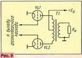
On the other hand, cascades based on pentodes and tetrodes in the maximum power mode P_ have a higher (0.35...0.4) efficiency. than cascades on triodes (0,15...0.25). Let us now consider the features of output transformers installed in single-cycle UMZCH operating in mode A. In such cascades, as is known, there is a constant magnetization of the transformer magnetic circuit, which can lead to a drop in its magnetic permeability and a decrease in the inductance of the primary winding, which is accompanied by a narrowing of the reproducible frequency band from the low-frequency spectrum. As follows from the formula for determining the inductance of a coil with a closed steel magnetic core (L=1,26nSmW2/Lc -10-8, H. where m is the magnetic permeability of the magnetic core; SM is the cross-section of the magnetic core, cm2; W is the number of turns of the coil; Lc is the average length of the magnetic field line, cm), the inductance of the primary winding of the transformer can be increased by increasing the number of its turns and the cross-section of the magnetic core. However, an increase in the number of turns is accompanied by an increase in magnetization, and an increase in the cross-section of the magnetic core leads to a sharp increase in the dimensions and weight of the transformer. In addition, the inductance actually grows very slowly. Let us illustrate the process of selecting the magnetic core and the number of turns of the primary winding of the transformer with the following example. Let's assume that we need to carry out this procedure for an amplifier stage with anode resistance of the output lamp Ra = 2 kOhm, anode current 1a = 0,2 A and useful power P_ = 24 W. It is known that the required inductance of the primary winding of the output transformer is determined by the formula L = 0,3 Ra/fn, H, which means that if we want the operating frequency range to be limited to fn = 20 Hz, then we must provide an inductance L = 0,3 2 10 3 /20=30 Gn. When using a magnetic core PL25x50xb5, which can only accommodate a certain number of turns, this is possible with the ratio of the primary winding resistance to the anode resistance Ro6/Ra = 0,3. A magnetic core with a large cross-section PL25x50x120 made it possible to reduce this ratio to 0,25, and PL32x64x16 - to 0,2. It is easy to see that increasing the cross-section of the magnetic circuit by three times leads to a decrease in the Ro6/Ra ratio from 0,3 to 0,2, and to obtain a well-developed low-frequency register, this ratio should be equal to 0,1, since otherwise due to the drop voltage on too high a resistance of the primary winding will reduce the efficiency of the output stage. If the range of reproduced frequencies is limited to 30 Hz, then the inductance of the primary winding will decrease to 20 H, and in this case, when using magnetic cores PL25x50x65, PL25x50x120 and PL32x64x160, the Ro6/Ra ratios will be equal to 0,23, 0,14 and 0,13, respectively. which is also more than the required 0,1. In order to still obtain the desired ratio, it can be recommended to increase the anode voltage of the output lamp, then, with a constant power transferred to the load, it will be possible to reduce the anode current, and therefore reduce the bias of the output transformer. In addition, you can increase the lowest frequency of the reproduced frequency range to 40 Hz and reduce the anode load resistance Rn by using lamps with low internal resistance Ri. Now let's move on to considering the operating features of the push-pull output stage (Fig. 9). This cascade imposes strict requirements on the symmetry of antiphase signals arriving at its inputs. The phase inversion cascade must ensure the fulfillment of these requirements.
From the point of view of ensuring the symmetry of the output signals, the best is a phase inverter made on two triodes connected in a balanced circuit (Fig. 10). Its symmetry depends on the parameters of the current generator in the cathode circuit of the phase inverter lamps.
To illustrate this statement, we present the harmonic spectrum and the coefficient of nonlinear distortion of the output signals of phase inverters operating with generators whose equivalent resistances are 11 and 30 kOhm (see table).
Measurements were carried out for three levels of the bass reflex output signal: maximum (+20 dB), nominal (+10 dB) and minimum (0 dB). It is easy to see that with an increase in the equivalent resistance of the generator from 11 to 30 kOhm, the harmonic coefficient of the output signal, determined by the symmetry of the phase inverter, drops by almost half. A lamp, transistor or ordinary resistor can be used as a current generator. Particular attention should be paid to the selection of pairs of lamps for the push-pull output stage. This is very important to do, since unbalance leads to a significant increase in the overall distortion at the amplifier output, as well as amplitude modulation of harmonics with a frequency of 100 Hz due to a decrease in the degree of suppression of power supply ripple inherent in all symmetrical stages. Recent studies conducted by the authors of the article have confirmed the need to select pairs of lamps based on the coincidence of current-voltage characteristics with an accuracy of no worse than 5...2% over the entire range of operating currents. To calculate a push-pull output stage operating in mode A, you can use the formulas for calculating single-cycle stages, only doubling the power P_. In the case of its operation in mode B, the calculation procedure changes somewhat [3]. Shown in Fig. 11, the dependence of the power supplied to the load P_ and the efficiency on the ratio Ron/Ri also confirms the fact that for a given anode voltage and operation in mode B without grid currents, the triode delivers the greatest power with an anode load resistance equal to its internal resistance Ri. The efficiency of the push-pull triode output stage in mode B increases with increasing Ron, tending to a value of 0,785.
In the case of using pentodes or tetrodes in a push-pull output stage, their most advantageous load when operating in mode B is one in which the load characteristic passes through the bend of the static anode characteristic, taken at a voltage on the control grid Uc = 0. In this case, the power supplied by the lamps to the load and the efficiency of the cascade are close to maximum. The anode load resistance of one arm of the push-pull cascade in mode B is less than in mode A, and is usually within the range (0.04...0.1) Ri. Otherwise, the push-pull cascade on pentodes is calculated in the same way as on triodes. It should be noted that in the output stages of real high-quality 3H amplifiers, pure mode B is never used due to the occurrence of step-type distortions inherent in this mode. Preference is given to AB mode. in which the lamps operate with a certain initial bias, which eliminates the occurrence of these distortions. Selecting an output transformer for a cascade operating in mode B is simpler than for a cascade operating in mode A, since there are no problems associated with permanent magnetization of the magnetic circuit. As for minimizing leakage inductance, it is achieved by sectioning both windings of the transformer. In conclusion, I would like to draw attention to such an amplifier parameter as the output impedance. It can be determined by the formula: Rout=[(Uxx/Uh)-1] Rh. where Uxx is the open-circuit voltage at the amplifier output, V; Uh - voltage at the amplifier load, V; Rh - load resistance. Ohm. This parameter most fully characterizes the dependence of the output current on the output voltage of the amplifier. In Fig. Figure 12 shows a diagram for connecting measuring instruments, suitable for removing this dependence. Measurements must be carried out at different frequencies. This relationship should be as linear as possible. Nonlinearity is corrected by introducing an environmental feedback system of sufficient depth.
The preamplifier is made according to a two-channel circuit and operates from magnetic pickups of traditional electronic control units, CD players and other sources of low-frequency signals. It provides finely compensated volume control, tone control for lower and higher sound frequencies, and stereo balance adjustment. The amplifier has two outputs and sockets for use with stereo phones. A tape recorder can be connected to one of the outputs, and an external UMZCH can be connected to the other. Basic technical characteristics of the amplifier. Nominal input impedance: magnetic pickup - 47, CD player - 10, universal - 100 kOhm; range of reproduced sound frequencies - 7...90000 Hz; tone control range for lower and higher sound frequencies - 6 dB; noise level (weighted value) - at the output of the magnetic pickup amplifier-corrector - 73, linear amplifier - 97 dB; output resistance - at least 1 kOhm; separation of stereo channels at a frequency of 10 kHz - no worse than 40 dB, maximum output signal at a load of 47 kOhm - no less than 25 V (rms) The connection diagram of the pre-amplifier blocks is shown in Fig. 13. It consists of four functionally complete blocks: a high-pass filter (A1), loudness compensation elements for volume control (A2), a two-channel amplifier (A3) and a power supply (A4). Outside the blocks there are five input (XS1-XS5) and three output (XS6-XS8) sockets, three switches (inputs - SA1, high-pass filters - SA2, loudness elements - SA3), stereo balance controls (R9, R10), volume (R11 , R12), timbre of lower (R13, R15) and higher (R14, R16) audio frequencies, indication elements (HL1-HL15), surge protector and power switch.
On the front panel of the amplifier case there are volume, tone and stereo balance controls, a network switch, a high-pass filter indicator, a loudness switch, an input switch and a telephone jack, and on the rear there are input and output jacks and a grounding jack. The signal from the input of the magnetic pickup XS2 goes to the input of the amplifier-corrector, and from its output to the input switch SA1. Signals from all other inputs are also supplied here, which then go to the High Pass Filters R1R2C1 (boards A1 L, A1.2). the filters are designed to limit the sound spectrum from lower sound frequencies (<18 Hz) and, if desired, can be turned off with the SA2.0 switch; when the filters are turned on, the HL1 LED signals. Through these switches and separate R9 stereo balance controls. R10 input signals go to volume controls 11, R12, and then to the inputs of the 3CH pre-amplifiers (boards A3.1 and A3.2). Using switch SA3, loudness compensation elements R11, R12, C1 can be connected to the taps of resistors R2, R1. C2 and R3. R4. C3, C4 (boards A2.1 and A2.2). From the output of the pre-amplifier (pin 19, 16 boards A3.1 and A3.2), the amplified signal is supplied to the output jack XS7 and to the input of the telephone repeater connected to the telephone jack XS8. The XS6 output jack is connected to the stereo balance control and is used, as mentioned above, when recording a signal to a tape recorder. A schematic diagram of one of the pre-amplifier channels (board A3.1) is shown in Fig. 14. The second channel is completely identical to it. The pins of its board are indicated in brackets next to the pins of the first channel (Fig. 14). The A3.1 board contains an amplifier-corrector for the magnetic pickup, as well as linear and telephone amplifiers.
When operating from a magnetic pickup, the input signal from jack XS2 (Fig. 13) through the passive high-frequency correction circuit R2C1 is fed to the input of a three-stage corrector amplifier. Its first two stages are made on a double triode VL1 according to a conventional resistive circuit with a load in the anode circuit. The third stage is assembled on a VL2.1 lamp according to a cathode follower circuit, which contributes to its good matching with a linear amplifier. To stabilize the operating mode of this cascade, the R8R9R12 circuit is used. The standard frequency response of a corrector amplifier is obtained thanks to two frequency-dependent circuits: a passive R2C1 and an OOS circuit, the voltage of which is removed from the output of the amplifier and, through elements R10R11C4, is supplied to the cathode of the input lamp VL1.1. The voltage from the output of the corrector amplifier (pin 10 of the A3.1 board) is supplied to the input switch SA1 and then in the usual manner - to the input (pin 12 of the A3.1 board) of the linear amplifier. The gain of the magnetic pickup corrector at a frequency of 1000 Hz is 38 dB; weighted signal-to-noise ratio - 72...74 dB; deviation of the frequency response from the standard when using elements R2, R5, R10, R11, C1, C4 with a tolerance of 1% - no more than 1 dB. The linear amplifier, like the corrector amplifier, is three-stage. Cascades on triodes VL3.1 and VL3.2 of the VL3 lamp are assembled according to the circuit of resistive amplifiers. The first of them, through resistors R15R16, is covered by a local OOS circuit, which reduces its output resistance. The third stage is a cathode follower. The voltage from its output is fed to the XS7 output jack and to the telephone amplifier. The tone controls R13 (LF) and R14 (HF), together with elements R19-R23 and C9-C11, operate in a common OOS circuit. Linear amplifier gain - 20 dB; weighted signal-to-noise ratio - 97...99 dB. The telephone amplifier is made according to a composite emitter follower circuit using transistors VT1-VT4. The voltage from its load is supplied to the XS8 telephone jack (see Fig. 13). The schematic diagram of the pre-amplifier power supply is shown in Fig. 15. AC mains voltage is supplied to it through a special high-frequency noise suppression filter L1L2C1C2 and power switch SA4. Network transformer T1 operates on three rectifiers. The anode voltage rectifier is assembled using VD5-VD8 diodes connected in a bridge circuit. The rectified voltage is supplied to the ripple smoothing filter R18C11-C14R16 and then to the electronic filter on transistor VT1 and zener diodes VD1, VD2. The latter protect the transistor from breakdown when the power is turned on. The operating mode of this filter is set by trimming resistor R12. At the output of the electronic filter, passive RC filters R1С1, R2C2, R3C3 and R4C4 are included.
The lamp filament voltage rectifier is assembled using VD9-VD12 diodes. Directly from its output (after smoothing capacitors C15, C16) through resistor R5, power is supplied to incandescent indicator lamps HL2-HL15. The filament voltage of the amplifier lamps is first supplied to the stabilizer using transistors VT2, VT3. The exact value of the stabilized voltage (+6,3 V) is set by trimming resistor R6. The voltage to power the telephone amplifier (-6,3 V) is rectified by diodes VD13-VD16, passes through the ripple-smoothing capacitor C17, the stabilizer on transistors VT4, VT5 and goes to the electrodes of transistors VT1-VT4 of the pre-amplifier board A3. The main amplifier blocks are mounted on a metal chassis with dimensions of 475X112x400 mm. All blocks use constant resistors C2-23 and C2-33 and trimmers SP4-1. The amplifier board (A3.1) contains capacitors K71-7 (C1, C4, C13, C16), K73-17 (C2, C5, C14), K78-2 (C3, C6, C7, C15), K77-7 (C9-C11, C13), K50-24 (C8, C17, C18), KD-2 (C12); on the power supply board (A4) - K73-17 (C1-C4, C6, C7, C10, C18-C20), K50-24 (C5, C8. C9, C15-C17); on the loudspeaker board (A2) - PM-2 (C1...C3) and K71-7 (C2. C4); on the high-pass filter board (A1) - K71-7 (C1); outside blocks - KM-5 (C1-C7) and K73-17 (C8-C9); in the surge protector -K73-17(C1,C2). Resistors SPZ-30 were used as stereo balance regulators, volume regulators - SPZ-30, tone regulators - SPZ-30. The network transformer of the pre-amplifier is made on a magnetic circuit Ш26Х52. Winding 1-3-5-7 contains 2x404 turns of wire PEV-2 0,315; winding 2-4 - 1078 turns of wire PEV-2 0,08; winding 10-12 - 36 turns of wire PEV-2 1,41; winding 6-8 - 31 turns of wire PEV-2 0,315. The shielding winding consists of 20 turns of PEV-2 0,1 wire, wound in one row. The line filter has DM-3 chokes (LI, L2). Network switch SA4 - PKN-41, high-pass filter switch SA2 - PKN61. the remaining switches SA1, SA3 are PGK. The power amplifier "UM-01" from Valancon can operate either from its own (see "Radio", 1998, No. 3, pp. 19-21) or from an external pre-amplifier. Its sensitivity is 0,775 V; rated output power - 2x100 W; maximum short-term power - 2x200 W; nominal range of reproduced frequencies - 7...90 Hz; frequency response unevenness in the range of 000...20 Hz - no more than 20 dB; signal-to-noise ratio - no less than 000 dB; dimensions - 3x97x475 mm; weight - 160 kg. The amplifier is designed to connect speaker systems with electrical resistance of 400 and 34 ohms. The connection diagram of the UMZCH units is shown in Fig. 17. The input stereo signal from jack XS1 through level controls R1 and R2 is supplied to the boards of linear (A1.1, A1.2) and then final (A2.1, A2.2) 3H amplifiers. The latter are loaded onto output transformers T1, T2, to the secondary windings of which speaker systems can be connected through sockets XS2 - XS3.
The schematic diagram of the linear amplifier channel mounted on the A1.1 board is shown in Fig. 18. The first stage of the amplifier is made using triode VL1.1, connected according to a circuit with a load in the anode circuit. The cathode circuit of this lamp (pin 3 of board A1.1) through the circuit R6C4 receives the common OOS voltage from the secondary winding of the output transformer T1. Its depth is strictly related to the parameters of the output transformer and the topology of the wiring connections. With 6P45S output tubes used in this amplifier, sufficient linearity of the amplifier is ensured at an OOS depth of 5... 15 dB. From the load resistor R5 of the VL1.1 triode, the amplified voltage is supplied to the triode grids of the VL2 lamp operating in the bass reflex stage. The cathode circuits of this lamp include a current generator made on a VL1.2 triode. Its purpose was described in detail in one of the previously published articles in this series. The bass reflex cascade mode is set by adjusted resistor R15 according to the maximum signal amplitude at the anodes of the VL2 lamp. Elements R13C9C5 correct the frequency and phase characteristics of the power amplifier. Their ratings depend on the specific output transformer and are selected in such a way as to obtain sufficient uniformity of the named characteristics. Resistors R4, R17 and capacitors C1, C2, C7, C8 provide additional filtering of the supply voltages of the linear amplifier lamps. From the outputs of the bass reflex stage (pin 7, 8 of board A1.1), 3H signals are supplied to the inputs of a push-pull final power amplifier (pin 7, 8 of board A2.1) on pentodes VL5, VL6 (Fig. 19). The bias voltage is supplied to their control grids from an external rectifier with a voltage of -120 V. The lamp currents are set by trimming resistor R1 and balance regulator R2. The anodes of the lamp (pin 23, 24) are connected to the primary windings of the output transformer T1. The circuit diagrams of the amplifier channels mounted on boards A1.2 and A2.2 are similar to those described. The pinouts of these boards are shown in Fig. 18, 19 in brackets.
The circuit diagram of the power supply (board A3) of the power amplifier is shown in Fig. 20. The mains voltage is supplied to power transformer T1 through the high-frequency noise suppression filter L1L2C3C4 and switch SB1. Five rectifiers are connected to the secondary windings of the transformer. From the rectifier, the voltage of +420 V (VD2 - VD5) powers the bass reflex stages, +400 V (VD6-VD9 and VD10-VD13) - the anode circuits of the output stage lamps, +175 V (VD14-VD17) - the first stages of linear amplifiers and circuits shielding grids of the output stage lamps, -120 V (VD18 - VD21) - grid bias circuits of the output stage lamps and the linear amplifier current generator lamp. All rectifiers are made using bridge circuits. To suppress high-frequency interference, the diodes are shunted with capacitors C14 - C3Z. Oxide capacitors C2 - C7, C11, C12, shunted by capacitors with a capacity of 0,1 μF, are used as elements that smooth out ripples. A zener diode VD120 is installed at the output of the rectifier for a voltage of -1 V.
The filaments of all power amplifier lamps are powered by alternating current from a separate winding 13 - 14 of the network transformer T1. The power amplifier is mounted on five boards (A1.1, A1.2, A2.1, A2.2 and A3). Outside the boards there are input and output sockets, signal level controls, output and network transformers, elements of the OOS circuit C1, C2, R3, R4 (see Fig. 17), a high-frequency interference suppression filter, a power switch and an additional socket XS1 (Fig. 20 ). All fixed resistors are C20-23 and C2-33. The linear amplifier uses capacitors K50-24 (C3), K73-17 (C2, C7); K71-7 (S9), K78-2 (S10, S11). All other oxide capacitors of the power amplifier are K50-27, capacitors, rectifier shunt diodes and smoothing filters are K73-17. Signal level regulators R1, R2 (see Fig. 17) - SPZ-4M, trimming resistors R15 (see Fig. 18) and R1, R2 (see Fig. 19) - SP4-1. The output transformers are made on magnetic cores Ш32Х64. Primary windings 5 - 1 and 1 - 6 each contain 444 turns of PEV-2 0,45 wire. The secondary windings are sectioned, and each section contains 26 turns of PEV-2 1,32 wire. The network transformer uses a magnetic core Ш40Х80. The primary winding 1-2 consists of 344 turns of PEV-2 1,0 wire. The secondary windings contain: 3-4 - 464 turns of wire PEV-2 0,16; 5-6 and 7-8 - 450 turns of wire PEV-2 0,45; 9-10 - 195 turns of wire PEV-2 0,16; 11-12 - 156 turns of the same wire, 13-14 - 11 turns of PEV-2 2,5 wire. Literature
Author: V. Kostin, Moscow
Machine for thinning flowers in gardens
02.05.2024 Advanced Infrared Microscope
02.05.2024 Air trap for insects
01.05.2024
▪ Where does the rumor come from ▪ The perfect snack for heart health ▪ Gastronomic preferences of cats ▪ Internet addiction is hidden in the genes
▪ site section Acoustic systems. Article selection ▪ article Earth and water swings. Tips for the home master ▪ article How does the heart work? Detailed answer ▪ article Head of the communication center. Job description ▪ article Efficiency of heat pumps. Encyclopedia of radio electronics and electrical engineering ▪ article Two AF power amplifiers. Encyclopedia of radio electronics and electrical engineering
Home page | Library | Articles | Website map | Site Reviews
www.diagram.com.ua |


 Leave your comment on this article: