|
|
ENCYCLOPEDIA OF RADIO ELECTRONICS AND ELECTRICAL ENGINEERING Dynamic memory chip DRAM - as a video camera. Encyclopedia of radio electronics and electrical engineering
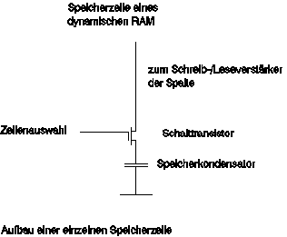
Encyclopedia of radio electronics and electrical engineering / Digital technology Entering images into a computer and its further digital processing one way or another requires quite large investments. The most expensive device here, perhaps, is a video camera, the signal from which is read, stored and digitized by a computer. The most expensive, but in terms of quality and the best method for capturing an image is to digitize the output signal from a consumer video camera. But at the same time, the circuitry costs here are still significant. Since it requires a high-speed digital-to-analog converter, a high-speed storage device and an appropriate interface to a personal computer. For amateur experiments, this is a rather expensive path. A television transmitting camera with a computer interface is too expensive, and can significantly undermine the radio amateur's budget. The way out of this situation was the unconventional use of a dynamic memory crystal. It turns out that DRAM can be used as a sensitive optical sensor. A few years ago, Micron Technology (an American manufacturer of integrated circuits on a single crystal) released a special version of 64k-DRAMS with a control window, which is sold as an image sensor. Since the geometry of the crystal in the microcircuit is known, with some effort it was possible to make a video camera. Unfortunately, these chips were no longer sold, which was an obstacle to the creation of a computer camera. However, I disassembled a computer board with DRAMS memory chips, which had a ceramic case with a metal cap. I removed the metal cover quite quickly, under it was a protective glass. What to do next? To successfully continue the experiment, it was decided to use the parallel port of a personal computer, which was the best suited for input / output information. Two small assembler programs were written for control. And - oh, a miracle! - after several tests, some kind of image could be seen on the computer display. How does this work? 64k-DRAM contains 65536 memory cells, which are arranged in a conventional access matrix. In this case, we used the D4164 chip from NEC, which is four matrices of 64x256 memory cells. Each memory cell consists of a capacitor and complementary transistors. A capacitor stores information in the form of an electrical charge. Complementary transistors access (switch) this capacitor.
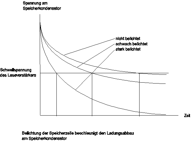
If a row of the matrix is selected, then switching in turn all 256 complementary transistors of this row connect the desired capacitor (cell) to one of the 256 amplifiers. If the voltage in the amplifier is above a certain level, then it is assumed that this is a logical 1, otherwise the output of the amplifier will be a logical 0. By counting one of the 256 amplifiers in this row (i.e. choosing the column address), we select the desired signal at the output DRAM. Since the capacitors on the memory chip leak (discharge slowly but inevitably), they must be constantly regenerated (recharged) in order not to lose their information. If they stop regenerating, then after a while the charge in the capacitor cell will disappear and the corresponding bit will be flipped. By illuminating (exposing) the capacitor, this effect will be enhanced, the capacitor will be discharged much faster, the result will be a flipping of a bit of information. The discharge time of the capacitor will be the main value of the light intensity in this memory cell. To use this effect, the following steps are required: - First, all memory capacitors are charged. - Then, for some time, the memory cells are irradiated. - All memory cells are interrogated and analyzed. Each cell (photocell) is viewed for inversion of the initial state, which will be regarded as a flare. DRAM is a memory chip, so the logical address allocation must match the physical location on the chip. To find out this distribution it is necessary to carry out several tests. In a DRAM chip, the cell addresses of which consist of two components - row addresses and column addresses, it can be assumed that they are located in the same way in the physical structure of the crystal. As it turned out, this is actually the case, i.e. logical row addresses correspond to physical rows; and logical column addresses correspond to physical columns. Logical addresses within a line correspond, of course, not to a physical location in a memory cell on an integrated circuit on a single crystal. In the processed image, this erroneous distribution is visible with rearranged rows and columns. Rearranging the bits of the address allows this defect to be eliminated, but, nevertheless, an experimental approach is still needed here. The geometry of integrated circuits on a single crystal of various manufacturers may be different. Therefore, the control program functions correctly only with NEC type 4164 chips. For other memory chips, errors may occur, but knowing the control principle, you can correct the result. Now it will be clear that our integrated circuit on a single crystal consists of four matrices that lie side by side. The two extreme matrices are separated from the two middle ones by relatively large gaps; this introduces some errors in the image. In these gaps is probably the decoding logic. The two middle matrices are separated by a much smaller gap so that they can be seen as a 128x256 matrix. On this basis, only two middle matrices are used as sensors. Looking through a magnifying glass at the microcircuit clearly defines the matrix structure of the crystal.
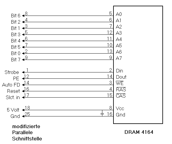
Now you need to accurately focus the lens. On closer examination, it is striking that there are still a few rows and columns rearranged. Two lines are displayed correctly, the next two are swapped with each other. The operation of reading the contents of the cells corrects this defect. Then there is another correction of the addresses of the columns, of which four are read correctly, and the other four are in the wrong order. Establishing the correct distribution is not always easy, as it requires solid integrated optics, and very precise focusing of the image. The pattern is clearly visible only when the distribution is correct! It is best to start testing with a white surface on which dark objects are placed and moved. Careful observation, precise focusing of the lens and some patience will help to recognize gross faults (mismatches) and then reveal the features of the integrated circuit on a single crystal. Gross inaccuracies are recognized with the help of black lines, localized on the crystal and taken under control. To use a personal computer's parallel port to connect a DRAM chip, some modification is required. The printer port contains parallel capacitors and equivalent series resistors that smooth out the steep edges of the clock signal; we don't need these elements in this case and so they should be removed.
In a typical highly integrated board, the individual modules are connected directly by CMOS outputs to the printer ports on a low-load bus, so there must be a bidirectional buffer driver. Now, using a cable, connect the parallel port to the socket on which the DRAM chip will be installed. The sockets of this panel must have good contacts (preferably gold-plated) and withstand repeated replacements, since you will have to select the necessary microcircuit. It is also necessary to bring out a separate power socket for the microcircuit, since the voltage at the output of the LPT port cannot be used here. The printer, however, cannot now be attached there! The decoupling capacitor between pin 8 and pin 16 of the DRAM is also very important, since a rather high electric current (about 100 mA) flows there when turned on. This capacitor is soldered directly to the IC's socket (note the polarity! Pin 8 is +5 volts, pin 16 is ground). Nothing works without this capacitor! Mechanical design of integrated optics The useful surface of the NEC 4164 chip chip is approximately 1,2x6 sq. mm, if we refuse both extreme matrices. Integral optics must be implemented and selected based on this fact. An 8mm lens corresponds to about a 50mm standard lens in a small format camera. Lenses with focal lengths from 5 to 35 mm are also taken into account. This optic pays for itself in further use. We used the mentioned lens from a Super-8 camera (focal length f = 25mm). It is better to use short throw lenses, such as those from old thin film cameras, a defective consumer TV camera, etc. In commission photo shops and photo studios, I hope you will be offered a suitable lens. But even without a high quality lens, good results can be achieved with a simple short throw lens. The quality of the image from the lens should not be inferior to the image received from the lens. After all, you are projecting an image onto a microcircuit chip, which does not support high resolution as on film. We cannot give a standard solution for the placement and design of the optical system here due to the large choice of lenses and its installation in front of the chip. It is only necessary to note the precise centering of the integral optics so that the image is accurately focused on the crystal. Light sensitivity The integrated circuit on a single crystal does not provide high light sensitivity, so the crystal exposure times are longer than those of a real CCD video camera. The speed of movement of fixed objects depends on the illumination and ranges from hundreds to 20 seconds. Longer times are not possible, otherwise the image is very "noisy" (blurred). During this rather long exposure period, it is advisable to have a tripod for your design. Also, your hands should be free to correct the exposure time by working on the computer keyboard and recording the successful images. It is noted that the DRAM chip crystal is more susceptible to the red spectrum of the optical range than to the blue one, it may have good spectral sensitivity in the infrared (invisible) spectrum of radiation. Software The initialization and reading of the memory chip is done by assembler programs that are inserted into Turbo-Pascal programs. Initialization The INITRAM procedure initializes the integrated circuit. Since the presence of a charge in the memory cells of the NEC 4164 chip corresponds to a logical "1", then "1" is pre-written in all cells. A number of complex clock signals are needed to control the DRAM chip.
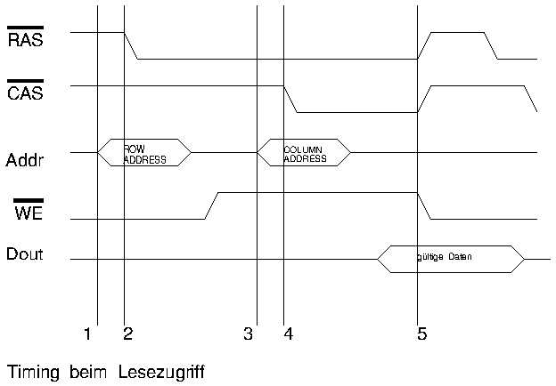
First, the line address counter is set at the address input of the microcircuit. In this case, the RAS input will be set to "0" - it is allowed to set the address of the line. Next, the column address is given, the Din input is set to the desired value (in our case, all cells are set to "1"), then the CAS input is set to "0". The DRAM has now received the column address and data bits. This process is repeated for all 32768 memories; now the DRAM chip is initialized, all capacitors are charged (written "1"). Then a certain period of time passes, during which the chip memory crystal is irradiated. When this time expires, information is read from the memory cells, while the highlighted cells will change their state (the illuminated capacitors will discharge faster). Reading information Reading information from the memory crystal is carried out by the LESERAM procedure. This will happen in the same way as in the INITRAM procedure. The contents of each memory cell will be stored in order to be converted into an image. In this case, local errors are corrected. Accordingly, every 8 bits are combined into bytes. It takes 4096 bytes to create an image because only half of the memory chip is used. This data will then be passed to the main program. The correction program equalizes the different sensitivity of individual pixels. (Memory cells at the edges of the sensor are more sensitive than the central area.) Since there is a small gap between both middle matrices (for NEC 4164!) there is also a second correction program. It pulls both halves of the image apart by 5 pixels and rationally fills the resulting gap. In some cases, it is more rational to abandon this correction or improve the processing algorithm. Three programs INITRAM (initialization), LESERAM (reading) and correction are contained in the "Exposure" procedure and are necessary for creating the time interval for irradiating the matrix and recording image information. The "ANZEIGE" (INDICATION) procedure is used to quickly display an image from a VGA card. In this case, information about the image is entered directly into the video memory, which significantly speeds up the result. Unfortunately, the vertical distances of individual memory cells double, which is explained by the compensation procedure in the display program. If other display adapters are used, this routine may need to be adjusted. The procedures "SPEICHERN" (Write) and "LESEN" (Read) write and respectively save the image in BMP format and dump it on the hard disk. Other programs The programs discussed above are used by other application programs. The "KUCKUCK" program is the most important of all; it records single images as well as series of images with 2, 4 or 10 brightness levels. The current image is always on the monitor and can be recorded using the spacebar. In principle, the camera can of course only take images with 2 levels (black and white), however, it is possible to repeatedly expose an image with halftones (greyscale).
Single exposures of halftone images are written sequentially to files (".3" and respectively ".9") and then converted for further processing by the programs "Grau3", "Grau4" and "Dither": "Grau3" produces 3 single exposures of a bitmap with 4 brightness levels. (4 bits per pixel of information, while using only colors 0, 7, 8 and 15 and, respectively, black, light gray, dark gray and white levels. For fast on-screen processing of grayscale images, another conversion is needed: the program "Grau4" converts the same input data in the same way as "Grau3", but in a different format. Nine single exposures for a ".9" file are converted by the "Dither" program into a black and white image (respectively 3 times the width and height of the original). As a result of the exposures, each pixel in the nine images for each point will create a 3x3 pixel random distribution matrix. The program "FilmAb" (Video clip) is used to view the created sequences of images, which in turn were created by the program "KUCKUCK". In this way, short "video clips" with 2 or 4 brightness levels can be created and the viewing order can be chosen in any order. Since the format of 128x256 pixels turns out to be quite large, especially the length of the lines is twice as high as the columns, you can use the "half format" with a resolution of 128x128 pixels. First of all, when executing the program "FilmAb" (Video clip), you need to rationally load this option in order to save disk space. The resulting individual images can be processed by Windows programs such as Paintbrush. List of individual procedures and programs: - VIDEO.INC contains high-level procedures: - INITRAM, INITRAM2: Initialization of the D4164 chip in full and half format respectively. - LESERAM, LESERAM2: Read image information. - ANZEIGE: fast input to VGA card. - LESEN: bitmap file with 2 colors, 128x256 and 128x128 pixels. - SPEICHERN: bitmap data, format as read - KUCKUCK: Recording in two formats - 2, 4 or 10 brightness levels. - GRAU3: Generates a 4 color BMP file from 3 single exposures (".3" -> ".BMP"). - GRAU4: Data with information for 4 bits of VGA card (".3" -> ".4") is generated. - DITHER: 9 color images (".2" -> ".BMP") are created from 9 single exposures. - FILMAB: 2 or 4 color bitmaps are merged into a movie (given a name: "name. BMP"). References: - Datenblatt IS 32 Optic Ram, Micron Technology A set of original documentation in a file kuckuck.zip (283 kB) Translator's Note This work, judging by the date the files were created, was written in 1992, when even 486 computers were a very cool thing. You may have to adjust the software for modern PCs. It may turn out that the computer's parallel port will not have to be modified (I don't want to lose my printer :-). As for the microcircuits used: - apparently it will not be easy to find NEC DRAM (I haven’t found one in my trash yet), and another company’s MS may not contain a metal cap. How then to get to the crystal? In general, my opinion is that this article is only a starting point for experimenting with this interesting problem. В source file there are a few more text files. I'll try to translate them too. Author: Martin Kurz, translated by Nikolai Bolshakov, rf.atnn.ru
Artificial leather for touch emulation
15.04.2024 Petgugu Global cat litter
15.04.2024 The attractiveness of caring men
14.04.2024
▪ Ancient people could see dinosaurs ▪ Glasses will always be clean ▪ Motherboard Gigabyte G1.Sniper Z87 ▪ Seagate Innov8 8TB Desktop Hard Drive ▪ SIMO PMIC Converter MAX77654
▪ section of the site Electronic directories. Article selection ▪ article Political science. Crib ▪ Article Deputy director for production. Job description ▪ article Automotive VHF FM tuner. Encyclopedia of radio electronics and electrical engineering
Home page | Library | Articles | Website map | Site Reviews www.diagram.com.ua |


 Arabic
 Bengali
 Chinese
 English
 French
 German
 Hebrew
 Hindi
Hindi Italian
 Japanese
 Korean
 Malay
Malay Polish
 Portuguese
 Spanish
 Turkish
 Ukrainian
 Vietnamese


 Leave your comment on this article: