|
|


 Arabic
 Bengali
 Chinese
 English
 French
 German
 Hebrew
 Hindi
Hindi Italian
 Japanese
 Korean
 Malay
Malay Polish
 Portuguese
 Spanish
 Turkish
 Ukrainian
 Vietnamese
|
ENCYCLOPEDIA OF RADIO ELECTRONICS AND ELECTRICAL ENGINEERING Hybrid UMZCH without environmental protection. Encyclopedia of radio electronics and electrical engineering
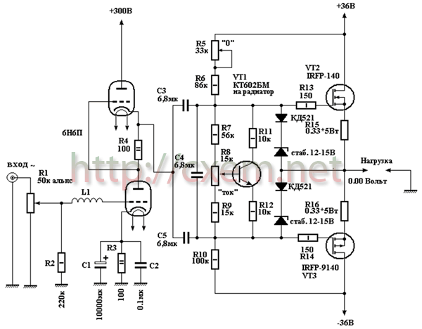
Encyclopedia of radio electronics and electrical engineering / Tube Power Amplifiers I present the design of the UMZCH, which in my opinion (ear) is the embodiment of all the best that we can take from modern transistors and vintage lamps. Power: 140 W Sensitivity: 1.2V
The circuit contains a small number of parts, is easy to set up, does not contain scarce and expensive components, and is very thermally stable. Briefly about the scheme The source follower is implemented on complementary MOSFET transistors IRFP140, IRFP9140 and has no special features. Transistor VT1 does not affect the sound, it is needed to stabilize the current when the temperature of the output transistors changes and is installed in close proximity to them on a cooling radiator. It is desirable to have a massive radiator with a large cooling area, to install transistors close to each other on a heat-conducting paste, through a mica gasket. Capacitor C4 provides a "soft" start source follower. Now about the driver I had to tinker with the driver, because. the input capacitance of one transistor is 1700 pF. Different types of lamps and different switching schemes were tested. We had to abandon low-current lamps, because. the blockage in the HF began already in the audio range. The result of the search was SRPP on 6N6P. With a current of each triode - 30mA, the frequency response of the amplifier extends from a few hertz to 100 kHz, a smooth decline begins in the region of 70 kHz. The 6N6P lamp is very linear, in addition, the 6N6P driver has a huge overload capacity. Triode modes 6N6P - 150V, 30mA. According to the datasheet Rmax.-4.8W, we have 4.5, almost at the limit. Who cares about 6N6P, you can ease the regime by increasing the values of the resistors R3 and R4, say, to 120 ohms. And yet, despite the fact that the 6N6P lamp has a small gain, it turned out to be prone to self-excitation, maybe the whole thing is in the copies I have, but, nevertheless, measures were taken to stifle this undesirable phenomenon. A standard aluminum screen was put on the lamp, the ninth leg was soldered to the ground, a small coil was installed in the grid - 15 turns of PEV 0.3 wire wound around a 150 kOhm - 1W resistor. If a smooth frequency response at HF is not the main thing for you, you can try in the 6N8S or 6N23P driver, and in the SRPP, of course. Setting up the amplifier is simple - set R5 to the middle position, and R8 to the lower position according to the diagram and turn on the amplifier. We warm up for 3 minutes, turn R5 - set "0" at the output, then carefully turn R8 - set the quiescent current of the output transistors. The current is controlled by measuring the voltage drop, on any of R15, R16 it should be - 110mV, which corresponds to a current through the output transistors of 330mA. The quiescent current is up to you - it all depends on the radiators and fans available to you. The amplifier setup is finished - enjoy the sound. I don’t bring the power supply, because. everyone can develop it himself. But I want to warn you that saving on a power supply is the last thing. Put large transformers, huge capacities and you will be rewarded. Don't forget to put fuses everywhere. Details The details are the most common, OMLT resistors, JAMICON capacitors, resistors R15, R16 are made up of three parallel-connected OMLT-2 - 1 Ohm, R8 is a wire, ALPS input potentiometer. The use of audiophile components is welcome, especially for power supply capacitors. Separately, it must be said about C3, C4, C5, the sound of the amplifier depends on them, so you better choose the type of capacitors to your taste. I have imported red-brown filmmakers of an unknown manufacturer, I suspect they are made in China. If you do not need the frequency response of the amplifier to be linear from 2 Hz, then the capacitances of capacitors C3 and C5 can be reduced. It is desirable to select the output transistors in pairs according to the parameters. When the amplifier is turned on, an alternating current background is heard for several tens of seconds, then it disappears. This phenomenon is due to the fact that the source follower has a large input resistance and while the cathodes of the triodes are warming up, the follower input is "suspended" and "accepts" the electromagnetic fields surrounding it with the frequency of the industrial mains. There is no need to deal with this phenomenon - you need to implement a delay in turning on the speakers. Amplifier power - 140W, with Uin.eff. - 1.2V. There is nothing to measure the coefficient of non-linear distortion, but I do not think that this amplifier has a horse, judging by the sound. Now about the sound The sound of this amplifier is similar to the sound of a triode push-pull, but the bass register is much "meater", the bass is fast, clear and solid. The middle is transparent and detailed, the tops are without the "sand" inherent in transistors. The amplifier eats everything, shakes any acoustics. The amplifier was conceived for outdoor use - a single-cycle tube at home, but now I'm not sure that it will not be the main one. Let's listen again. And yet, when building an amplifier, it is desirable to equip it with a system of all kinds of protection, this will improve its performance and protect your speakers from emergency situations. Author: Vladimir Petrushishin; Publication: cxem.net
Machine for thinning flowers in gardens
02.05.2024 Advanced Infrared Microscope
02.05.2024 Air trap for insects
01.05.2024
▪ A new source of green energy ▪ LMZ10501 - DC/DC nanomodule with load current up to 1 A ▪ Cartilage repair with a printer ▪ Artificial intelligence will look for extraterrestrial life
▪ section of the site for the Musician. Selection of articles ▪ article Sadly, I look at our generation! Popular expression ▪ article Table of the nutritional value of products. Travel Tips ▪ article New Year's garlands. Encyclopedia of radio electronics and electrical engineering
Comments on the article: Nicholas Yes, I assembled this amplifier, it really works perfectly, as described in the article. Do it + you won't regret it! Vladimir The amp is just amazing! Make a short path, quality food and you will be rewarded! Also, it is desirable to short-circuit both terminals of the capacitor C4 to ground with 200 Ohm resistors, before the lamps warm up, through a time relay, or with simple toggle switches. Then, you will not have jumping speakers and burning output transistors. Vyacheslav What is the real output power? Maybe 14, not 140 watts? Sergei The amp repeated (with a slight correction) - the sound pleased. Thanks to the author!
Home page | Library | Articles | Website map | Site Reviews
www.diagram.com.ua |

 Leave your comment on this article: