|
|
ENCYCLOPEDIA OF RADIO ELECTRONICS AND ELECTRICAL ENGINEERING New Year's garlands. Encyclopedia of radio electronics and electrical engineering
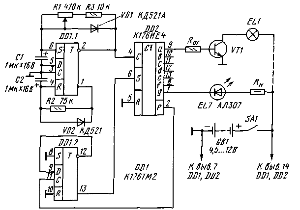
Encyclopedia of radio electronics and electrical engineering / Color and music settings One of the most wonderful holidays is approaching - the New Year. And, of course, in many homes a green beauty will take its rightful place, on the branches of which light bulbs of multi-colored garlands will be placed. And in order for the garlands to shimmer with all the colors of the rainbow, they must not only be painted, but also connected to an automatic switch. Some variants of such a machine are described in the proposed selection. Light effects machine It is not always possible to place a large Christmas tree in the room, more often a small branch is installed instead. In this case, they dress it up with small-sized lamps and LEDs that can be connected to the machine, made according to the diagram shown in the figure. Compared to devices that feed one, two or three garlands, this machine is able to control seven garland loads. Moreover, it is permissible to use a single light source as garlands - a miniature incandescent lamp, for example, of the SM type or an LED of the AL 102, AL307 series. If desired, the load can be made up of two or three such sources connected in series. The machine is powered from a 4,5 ... 12 V source, which is used as a battery, two 3336L batteries connected in series or a power supply unit. The machine uses two microcircuits. On the trigger DD1.1, a pulse generator is made, the frequency (and duty cycle) of which can be changed by a variable resistor R1. Trigger DD1.2 is enabled according to the counting trigger circuit - its inverse output (pin 12) is connected to input D (pin 9), and input C (pin 11) receives pulses from the overflow output P (pin 2) of the counter-decoder DD2.
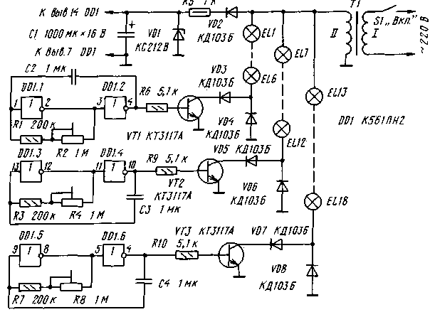
The direct output of the trigger DD1.2 (pin 13) is connected to the input S (pin 6) of the counter-decoder DD2. After the tenth pulse arrives at the input C of the counter-decoder, the state of the trigger DD1.2 changes to the opposite, which causes a change in voltage at the outputs ag of the counter-decoder to which the loads are connected. When using small lamps, they are connected to the outputs of the DD2 microcircuit through a matching stage made on a transistor that allows the corresponding collector current. A limiting resistor Rog must be installed in the base circuit of the transistor, the resistance of which must ensure saturation of the transistor. In the case of using LEDs, each of them must be connected through a resistor Rn. Of course, miniature lamps and LEDs can also be mounted on a Christmas tree branch - the lighting effect will only increase, especially with the appropriate color of the lamps and the selection of LEDs of different glow colors. The duration of the glow of the garlands and the pauses between their ignition depends on the frequency of the pulses received at the counting input of the DD2 microcircuit. Smoothly this frequency can be changed by a variable resistor R1, and roughly - by selecting capacitors C1 and C2. Since the generator frequency depends on the total resistance of resistors R1 and R3, as well as resistor R2, connecting in parallel or in series with them (and possibly instead of R2 or R3) a thermistor that has thermal contact with one of the garland lamps will give an interesting effect. Now the duration of the state of the counter-decoder outputs will change automatically and almost predictably. The same result can be achieved by switching on instead of KD521A diodes of the D2, D18 or other series with a photoelectric effect, and placing them near the bulbs of incandescent lamps. Instead of those indicated on the diagram, it is permissible to use K561TM2 (DD1) microcircuits. K176IEZ (DD2). Fixed resistors - MLT-0,125, their ratings are not critical for the normal operation of the device. Author: A. Romanchuk Novikovo, Sakhalin region Small Christmas tree garland switches Small-sized Christmas trees, including artificial ones, have become more and more popular lately. But the choice of industrial lamp garlands for them is small, so you have to make them yourself. Moreover, one of the most important requirements for them is maximum safety, the absence of a galvanic connection with the lighting network. One option, according to the author, is to use the step-down transformer available to many radio amateurs to power a low-voltage low-power soldering iron. Typically, such a transformer on the secondary winding has an alternating voltage of 12 to 36 V, and the power of the transformer is 20 ... 40 W. Such a voltage and power is quite enough to power garlands of miniature incandescent lamps of the SMN type - they are easy to paint in different colors and easy to mount on the branches of a Christmas tree. It should be noted that automatic switches, which use a sharp and frequent inclusion of garlands, and as a rule, are not very durable due to the heavy duty of the lamps and the rapid burnout of their filaments. More reliable is the mode in which the brightness of the lamps changes abruptly not from zero to maximum, but from 30 ... 40 to 100%. It is on this principle that the switch is built, the diagram of which is shown in Fig. 2.
The switch contains three identical channels, each of which consists of a pulse generator on two logic elements and an electronic key on a transistor. The generators are powered by a parametric voltage regulator R5VD1C1. Alternating voltage from the secondary winding of the transformer is fed to garlands consisting of incandescent lamps connected in series. In this case, the current in the negative half-cycles of the voltage at the upper output of the secondary winding according to the circuit flows through all the garlands and diodes VD4, VD6, VD8. The lamps of the garlands glow no more than half-heartedly. At the same time, voltage pulses from the generators are fed to the bases of the transistors. If the generator output has a high logic level (logic 1), the transistor will open through it, as well as the VD3 diode for the first garland (VD5, VD7 for the second and third, respectively) current will flow during the positive half-cycle of the voltage at the same output of the secondary winding. The garland lamps will glow at full brightness. Since the generators operate independently of each other and at different frequencies, the garlands switch independently of each other, which creates the illusion of a transfusion of light.
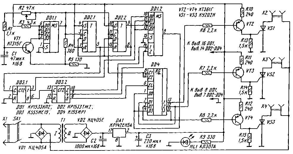
Most of the switch parts are placed on a printed circuit board made of one-sided foil fiberglass. Instead of those indicated in the diagram, diodes KD102B, KD105B and similar ones, designed for a pulsed current, about ten times the current consumption of incandescent lamps, the VD1 zener diode - any low-power one with a maximum stabilization current of 20 ... 30 mA and a voltage of 10 ... 12 V. resistors - MLT, S2-33, interlinear - SPZ-3, SPZ-19, SP4, SPO. Capacitor C1 - oxide K50-6, the rest of the capacitors - KM, K73. The choice of other parts largely depends on the voltage on the secondary winding of the transformer, the power and the number of incandescent lamps. If, for example, the voltage on the secondary winding is 36 V, and each garland uses 6,3 V lamps with a current consumption of 20 mA (six lamps connected in series) or 40 mA (two garlands connected in parallel with six lamps each), then diodes VD3-VD8 can be used as indicated above, and transistors - KT602A, KT602B, KT608A, KT608B, KT815B-KT815G or indicated in the diagram. If the current consumed by the garlands is higher, you will have to add a transistor to each channel (Fig. 3) or install composite transistors in place of VT1-VT3, for example, KT829A-KT829G or similar, and also use VD3-VD8 diodes, designed for the appropriate current. With a lower voltage on the secondary winding, the resistance of the resistor R5 should be proportionally reduced. The establishment of the machine comes down to setting the frequency of switching garlands with trimmers R2, R4, R8 (smoothly) or by selecting capacitors C2-C4 (roughly). Author: I. Nechaev, Kursk From the editor. Diodes VD3, VD5, VD7 protect the corresponding transistors from reverse voltage in case of failure of the diodes VD4, VD6, VD8. In most cases, these diodes can be omitted. Three string switch The switch (Fig. 3) allows you to get the effects of "running lights", "running shadow" and "accumulating" turning on - off garlands. Repeated several times, one effect is replaced by another. The direction of switching garlands is also periodically reversed. The device uses a rarely used method for obtaining the mentioned effects. A master oscillator is assembled on the multiplexer DD1.1 and transistor VT1. The frequency of the pulses generated by it can be smoothly changed by a variable resistor R2 over a wide range. The construction of the generator on one of the multiplexers of the DD1 chip made it possible to reduce the total number of chip packages. The information inputs of the DD1.1 multiplexer are connected together, therefore, with any signals at the address input, it works as a repeater. The signal from the output of the master oscillator is fed to a frequency divider by three, made on triggers DD2.1 and DD2.2. The duty cycle of the signal at the output of the trigger DD2.1 is 3/2, and at the output of the trigger DD2.2 - 3. An eight-bit counter assembled on the DD3 chip is connected to one of the outputs of the frequency divider. A three-bit reverse shift register is built on the DD4 chip. The role of the information input of the register is played by the inputs D0 and D3 connected together. At a low logic level at the input EL, information is shifted to the right, and at a high logic level, to the left. The direction of switching of garlands depends on the voltage level at this input. The combined clock inputs C1 and C2 receive pulses from the master oscillator. The sequence of pulses supplied to the input of the register is formed using the multiplexer DD1.2. If code 0 is applied to the address input, high-level pulses with a duty cycle of 4/3 are received at the input of register DD2, their frequency is three times less than the frequency of the master oscillator. In this case, the sequence of ignition of the garlands corresponds to the effect of "running lights". When code 2 is present at the address input, pulses of duty cycle 3 appear at the output of the multiplexer. In this case, a "running shadow" effect is formed. If the code is 1 or 3 at the address input, the signal from the output of the first bit of the counter DD3.1 passes to the output of the multiplexer. The signal has the shape of a meander, and the pulse frequency is six times less than the frequency of the master oscillator. Such a sequence of pulses is necessary to obtain an "accumulating" switching on - switching off the garlands. The automatic change of effects and the direction of switching garlands occurs due to the fact that the address inputs of the DD1.2 multiplexer, as well as the control input EL of the DD4 register, are connected to the higher bits of the counter on the DD3 chip. When the power is turned on, random information appears in the DD4 register, but it is not required to be pre-set, since during the first three periods of the generator this information is "pushed" out of the register. On transistors VT2-VT4 and trinistors VS1-VS3, electronic keys are assembled that control garlands connected to sockets X2-X4. The power supply of the device includes a step-down network transformer T1, rectifier bridges VD1 and VD2 and a stabilizer on the DA1 chip. The switch uses digital microcircuits of the K155, K555, KR1533 series. The integral stabilizer DA1, in addition to that indicated in the diagram, may be KR142EN5V. Transistors - any of the KT315, KT3102 (VT1), KT316, KT3107 (VT2-VT4) series. In place of the VD1 bridge, there can be KTs402 or KTs405 with letter indices A, B, F, I, and in place of VD2 - any of these series. Trinistors - KU201K, KU201L, KU202L-KU202N. LED HL1 - AL307 with any letter index. Capacitors - K50-35, K50-40. Fixed resistors - MLT-0,125, variable R2 - SPZ-4AM. A step-down transformer with a voltage on the secondary winding of 7 ... 10 V at a load current of at least 300 mA. Most of the parts are mounted on a printed circuit board made of double-sided foil fiberglass. Since the machine has a galvanic connection with the network, the board must be placed in a case made of insulating material, on the wall of which sockets X2-X4 should be fixed to connect garlands. A device correctly assembled from serviceable parts does not need to be adjusted. If it is necessary to change the frequency of the master oscillator, capacitor C1 should be selected (the frequency is smoothly regulated by a variable resistor R2). The sequence of effects and the direction of switching garlands can be changed by connecting the outputs of the frequency divider (DD2) and counter DD3 to the information inputs of the DD1.2 multiplexer and the EL input of the DD4 register. Author: A. Shitov, Ivanovo; Publication: N. Bolshakov, rf.atnn.ru
Traffic noise delays the growth of chicks
06.05.2024 Wireless speaker Samsung Music Frame HW-LS60D
06.05.2024 A New Way to Control and Manipulate Optical Signals
05.05.2024
▪ Backpack with six robotic arms ▪ MD Elite A-series Richland processors
▪ section of the site Microphones, radio microphones. Article selection ▪ article Who discovered the atom? Detailed answer ▪ article Building a fire in the parking lot. Tourist tips ▪ article Guessing a card from a row. Focus Secret
Home page | Library | Articles | Website map | Site Reviews www.diagram.com.ua |


 Arabic
 Bengali
 Chinese
 English
 French
 German
 Hebrew
 Hindi
Hindi Italian
 Japanese
 Korean
 Malay
Malay Polish
 Portuguese
 Spanish
 Turkish
 Ukrainian
 Vietnamese


 Leave your comment on this article: