
|
|
ENCYCLOPEDIA OF RADIO ELECTRONICS AND ELECTRICAL ENGINEERING VHF block. Encyclopedia of radio electronics and electrical engineering
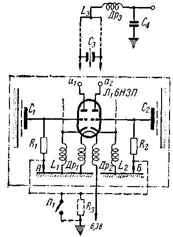
Encyclopedia of radio electronics and electrical engineering / Civil radio communications For field equipment in the ranges of 144 and 420 MHz, 6NZP lamps are the most acceptable of running lamps. With equipment assembled on these lamps according to push-pull circuits (Fig. 1), it is possible to remove not only an increased power of the order of 1,5-2,5 W, such equipment is more stable in frequency and less capricious in establishing and operating under certain conditions. On VHF, circuits with a grounded (common) grid are the most successful, but in order to reveal their advantages, it is necessary that the inductance in the grid (common electrode) circuit be reduced to the limit, so that the cathode circuit, which is under RF voltage, is isolated from the filament circuits or the last must have the same RF potential with the cathode. Usually in amateur designs these conditions are not met, and therefore we will explain their meaning in more detail. In the VHF band, details such as blocking capacitors, RF chokes, and even mounting wires are complex electrical circuits. Depending on the operating frequency, a capacitor of a certain design may have the character of either a "pure" capacitance, or an inductance, or even features of a tuned LC circuit. For example, a tubular ceramic capacitor KTK with a capacity of 51 pF with a length of connecting wires of 2-9 mm is a series resonant circuit at a frequency of 155-160 MHz, at a frequency of 50 MHz it still works as some kind of capacitance, at a frequency above 160 MHz - as an ever-increasing "inductance". The same behavior is observed in HF chokes - in the case of a large distributed winding capacitance (its value is mainly determined by the diameter of the choke frame), starting from a certain frequency, the choke becomes like a capacitance. These features of the behavior of parts on VHF can dramatically change and complicate the operation of any VHF device with an increase in the operating frequency. The fact is that in a conventional generator there should always be two tuned circuits, one of which determines the operating frequency, and the second determines the feedback conditions. Such two-circuit systems (in VHF circuits the second circuit is not always explicitly expressed) are easily tuned, stable under load, and can operate in a wide frequency range. An unsuccessful part, an extra HF choke, long wiring to the ground point of any part, etc., can introduce a third, extra circuit into the VHF generator system, which creates a complex unstable system, and hence there are generation failures in the range, a sharp decrease in power, frequency instability and its abrupt change from random influences, etc. Setting up such a system is very complicated and comes down, in essence, to finding an extra "parasitic" circuit in the generator. There is only one conclusion - it is necessary to use less HF chokes, select small diameters of their frames and the wire itself, in some cases replace HF chokes with resistances of the order of 1-2 kΩ. All decoupling capacitors must have a minimum length of connecting wires. On VHF, it is convenient to make such capacitors in the form of flat plates pressed to the chassis through a gasket made of mica, foil, plastic, etc., or to use special industrial samples of VHF decoupling capacitors. In VHF designs, it is very important to first "fit" the location of all the details of individual RF units, up to the creation of a temporary layout from the proposed details. The design of the high-frequency unit All of the above principles are applied in the design of the RF unit, which can be used as the main structural element for various VHF devices in a wide frequency range. The RF unit is assembled according to a push-pull circuit on a lamp with a grounded grid (Fig. 1).
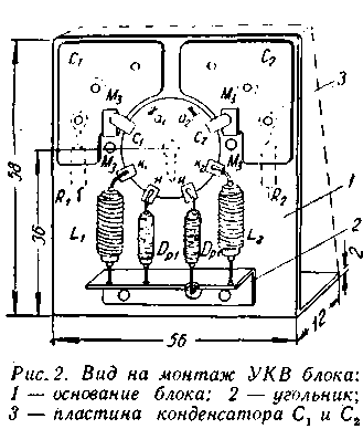
All parts of the circuit, circled by a dotted line, are mounted on a rigid metal base around the ceramic socket of the 6NZP lamp (Fig. 2). The base itself (detail 1 in Fig. 2) is made of solid aluminum 1,5-2,0 mm thick or brass 0,8-1,0 mm thick. In the case of thinner aluminium, the edges of the base must be bent for greater rigidity.
This design is also convenient for those cases when the entire device needs to be shielded. The external dimensions of the base 58x56 mm (Fig. 2) should be considered as minimal when assembling the RF unit from standard parts. At a height of 36 mm from the edge of the base, holes are made: one with a diameter of 21,5 mm and two with an M3 thread for attaching a ceramic nine-pin socket of a 6NZP lamp. Above the socket on the base plane, two plates (Fig. 3, a) of flat capacitors C1, C2 are attached, made of flat brass or copper sheet with a thickness of 0,6-0,8 mm. During manufacture, the part of the plate shown by the dotted line in Fig. 3, a, is incised with a jigsaw and bent up in the form of a bracket (Fig. 3, b). Petals from the grids of lamps are later soldered to these brackets. To the base of block 1, plates 3 (Fig. 2) are fastened with two M2 screws according to Fig. 3, b, which shows the assembly of the entire assembly, including the fastenings of the leakage resistances of the grids R1, R2.
The screws pass through holes with a diameter of 4 mm and base 1 and are isolated from it by means of bushings. Bushings are made of ebonite or organic glass. When assembling capacitors C1 and C2, a mica plate 3-1 mm thick or less is laid between plates 0,1 and base 0,12. For the symmetry of the capacitance of the capacitors, it is important that the spacers are made from the same sheet of mica. The capacitance of capacitors C1, C2 is about 105-110 pF. Mica plates can be removed from old large size KSO capacitors. Do not use mica from old soldering irons. When assembling capacitors, instead of washers, a brass petal is inserted under the head of the M2 bolts, to which one end of the resistance of the grids R1, R2 is soldered. Fastening plates 3 with two bolts is somewhat difficult, but it gives a more uniform fit of the plates to the base and ensures the equality of capacities C1, C2. After assembly, the capacitor must be checked for breakdown at a voltage of 250-300 V; testing with a tester for the absence of a short circuit is not enough. At the lower edge of the base 1, an angle 2 is attached to it with two bolts M3, M2 or rivets, made of a strip of copper (brass) 0,4-0,5 mm thick (see Fig. 3, d). On the reverse side of the base, under the fastening nuts of screws or rivets, brass petals are placed, to which the ends of the resistances R1R1 are soldered (see Fig. 3, c). The output of the second filament inductor passes through a hole with a diameter of 4 mm on the reverse side of the base and is centered in this hole with a small piece ("bead") of an elastic insulating material (rubber, polyethylene from the PK-1 cable, etc.). In the case of using an RF block in the transceiver circuit, resistances R1, R2 must be isolated from the chassis (points A, B in Fig. 1). To do this, on the reverse side of the base, under the mounting screws of the elbow 2, a strip of insulating material with two or three mounting petals is placed to fasten the ends of the resistances R1, R2. In this case, the filament output is rigidly attached to the same bar. The filament petals, cathodes and grids of the lamp socket are carefully bent at a right angle and partially cut off (by 1 mm to the hole in the petal). Conclusion 5 of the inner screen between the 6NZP triodes and the central mounting tab of the panel are cut off. The petals of the anodes a1, a2 remain straight, but their the plane is carefully rotated with pliers by about 30-40 ° so that they are parallel to the vertical edges of the base. Line segments are then soldered to these petals, forming the anode circuits of the generators. Installation of eight parts in the described way (Fig. 1) creates a VHF unit. It provides the structural rigidity and constancy of circuit parameters necessary for VHF, is suitable for a wide frequency range with easy replacement of parts and, most importantly, does not require industrial parts and, therefore, can be repeated anywhere. Depending on the purpose and range of operating frequencies in the VHF unit, it is necessary to change the values of inductances in the cathode, external anode circuits and associated elements of connection with the load. When using a VHF block for the design of inductance generators L1, L2, the desired feedback phase is determined, while the feedback value in the circuit itself is determined by the ratio of intra-tube capacitances. In the case of using the unit as an RF inductance amplifier. L1, L2 with the cathode-grid capacitance are tuned to the operating frequency, and the feedback in the circuit is neutralized by the introduction of additional capacitances. All further discussion refers to the VHF unit used in the mode of VHF generators or super-regenerators. Design of oscillatory circuits The anode circuits connected to the VHF unit, in our case, are made in the form of a quarter-wave segment of a two-wire line on both 144 and 420 MHz bands. The use of lines provides high efficiency, increased frequency stability, stability of operation. Depending on the range, these lines and tuning organs are performed differently. Range 420-435 MHz To reduce the wave resistance, the line is made of a strip of red copper 13 mm wide, the thickness of the strip is 0,6-0,8 mm (Fig. 4, b). A sketch of the tuning body is shown in fig. 4, a. The open ends of the line are soldered to the anode petals a1, a2 of the 6NZP panel (see Fig. 1), the latter being superimposed on the outer sides of the strip. The short-circuited end is attached to the main chassis of the device using an angle (Fig. 4, c) made of any insulating material.
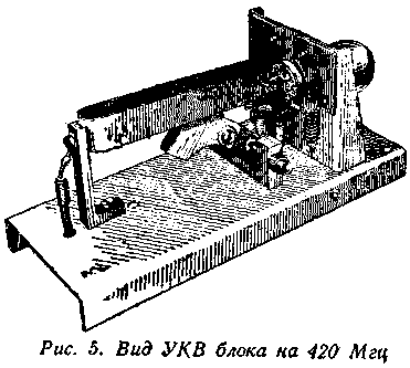
The elbow and the line are fastened with an M2 screw, under the head of which a brass petal is inserted to solder the end of the Dr3 anode choke (see Fig. 5). Tuning in the range of 420-435 MHz is achieved by introducing an additional variable capacitance C3 at the open end of the line. The stator of this capacitor is the strips of the line itself, the rotor is made in the form of a U-shaped "flag" on a rotary mechanism (Fig. 4, a, 4, d). The "flag" is made from a strip of red copper 0,5 mm thick and is first attached to a block (Fig. 4, e) made of organic glass (M2 screw) and only through it - to the axis of rotation (Fig. 4, h). The axis is made of steel wire with a diameter of 3 mm, has an M3 thread at both ends and fits into the holes of the rack (Fig. 4, g), also made of organic glass. The stand is attached with a rotor to the main chassis of the device at a distance of 25 mm from the lamp socket. With this position and the distance between the "flag" and the line of 0,5 mm on each side, the frequency range of 418-437 MHz is overlapped.
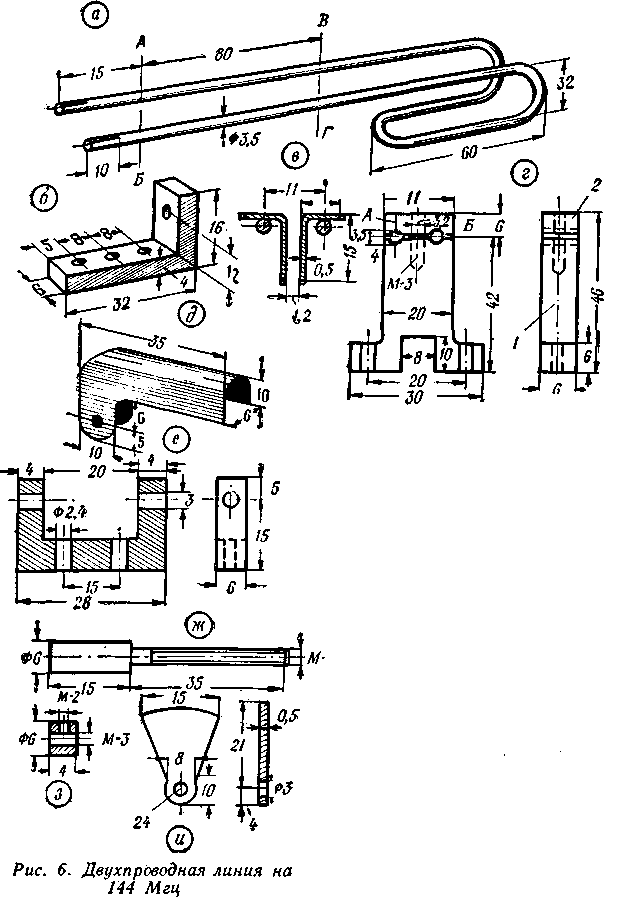
It should be recalled that the strip from which the line and the "flag" are made must be carefully aligned, polished and covered with a colorless varnish if it is not possible to silver them. This significantly increases the quality factor of the line during long-term operation. Range 144-146 MHz All main design details are shown in Fig. 6. The line of the anode circuit (Fig. 6, a) is made of smooth copper wire with a diameter of 3,5 to 4,5 mm. The total length of the unbent line is 250 mm.
To reduce the dimensions of the device and to facilitate communication with the antenna, the anode line is partially bent at the short-circuited end. At the open end, longitudinal slots are made in the wires of the line with a jigsaw, into which, during installation, the anode petals a1, a2 (Fig. 1) are soldered from the 6NZP socket. The short-circuited end of the line is attached to the main chassis of the device using an angle (Fig. 6, b) made of any material. For normal operation of the generator, it is important that the lower edge of the curved line is at least 10 mm away from the chassis. The line and the square (Fig. 6, b) are fastened with an M2 screw, for which an M2 thread is made in the center of the bend of the line. If such fastening is not possible, then a wider plate is soldered to the short-circuited end and the fastening is done on the M2 screw. The elbow with the line is screwed to the main chassis. In the fourth hole of the square, a brass petal is fixed with an M3 screw, the "cold" end of the inductor Dr4 and the decoupling capacitor C1 are rigidly soldered to it (see Fig. 6). In the section A B of the line (Fig. 6, a), plates of an additional capacitor are attached (Fig. 6, c) to fit into the range (without this capacitor, the line should be even longer). In the cross section of the VG line, a support post made of good insulating material is strengthened for greater rigidity and constancy of the generator frequency (Fig. 420, d). It is desirable to have two such racks for generators that must operate at fixed frequencies. For variable frequency generators, this complicates tuning. The tuning organ, in principle, is made in the same way as in the range of 435-6 MHz (Fig. 6, e, 6, g, 6 h, 4, i), but the flag is longer, it is mounted on an insulating block (Fig. 6, e). On the. rice. 35e shows a somewhat modified design of the tuning axis. The stand with the tuning element is fixed under the line at a distance of 0,5 mm from the lamp panel and is located perpendicular to the line. By changing the gap between the flag and the line wires (usually 3 mm), you can get a stretch over a range of up to 10 MHz. If it is necessary to cover a wide range (15-7 MHz), tuning can be done with a flag inserted between the plates of an additional capacitor (see Fig. XNUMX, which shows both types of tuning). The line support post (Fig. 6, d) is made of organic glass according to the dimensions of the already fixed anode line and then cut with a jigsaw along line A B. Part 1 is attached to the main chassis under the line at a distance of 95 mm from the 6NZP panel, the upper part 2 is then superimposed over the line and is tightened with an MZ screw (shown by a dotted line in Fig. 6, d). The remaining details of the VHF block circuit (Fig. 1): chokes, inductances, resistances vary depending on the operating frequency ranges. Practice shows that the applied chokes Dr1, Dr2, Dr3 work equally well at both 144 and 420 MHz. All of them are wound on rigid frames. Particularly convenient for this purpose are the old resistances of the TO type, since the hard silver-plated terminal is located in the center of the frame. TO resistances for 0,25 W have a diameter of 3 mm, resistances for 0,5 W - 5 mm. For frames, TO resistances of the order of 10 kΩ and higher are used. All details of the VHF unit are given in Table. 1.
Communication with the antenna is carried out by a communication loop symmetrically located relative to the anode line (Fig. 7).
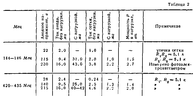
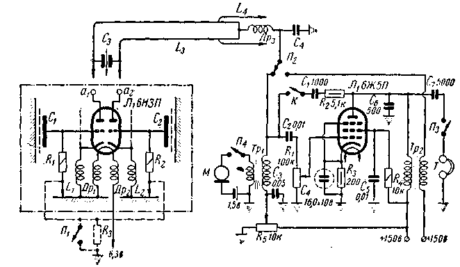
The length of the loop and the degree of coupling depend on the properties of the antenna used. For the 420 MHz range, its length is approximately 30-40 mm, for 144 MHz - 60-80 mm when using 5-element matched antennas. Setting up oscillator circuits Repeatedly repeated designs of the VHF block (in different places and by different designers) showed the high reliability of the block in operation. Some deviations usually occur due to deviations in the design of lines and tuning elements. The necessary tuning limits are selected by slight changes in the distances between the line strips by 420 MHz or by changing the distance of the plates of the additional tuning capacitor in the 144 MHz range. An increase in range stretching can be obtained by approaching the setting elements to the short-circuited end of the line. For these works, a VHF wavemeter or a rigidly mounted two-wire line is required. The final frequency adjustment must be done with the antenna or other load turned on and optimal connection with the anode line. The connection with the antenna is selected so that the grid current drops to approximately half of its value without load or at the maximum radiation, controlled at a certain distance from the antenna using any field indicator. Feedback in the generator circuits (Fig. 1) is obtained due to the capacitance of the anode-cathode circuits Cak. This capacitive coupling is quite sufficient for normal operation at 420-435 MHz (it can be judged by the value of the grid current, which should be approximately 15-20% of the anode current). However, in the range of 144-146 MHz, this connection is not enough and it must be strengthened by introducing an additional capacitance Sac. This is done using two pieces of wire with a diameter of 0,8-1,0 mm, a length of 60 mm, bent in the form of brackets with a distance between the wires of 8-9 mm. One end of the brackets is slightly bent and soldered to the cathode leaves in such a position that the opposite side of the bracket is parallel to the anode line. The distance of the bracket wires to the line of about 3-4 mm is not critical, this weak connection (fractions of a picofarad) significantly increases the power of the generator. Approximate operating mode of the generators is given in Table 2. Incandescent bulbs 6,3v x 0,28 a or 18 v x 0,1 a, as well as 12 v (5,0 W), connected directly at the short-circuited end of the line with the selection of the most advantageous connection, were used as a load. It is interesting to note that due to the higher quality factor of the anode circuits, generators without load begin to work already at 25 V of the anode voltage. Reducing the resistance in the grid circuit R1, R2 to a value of 4,3 k (at 144 MHz) increases the power by 0,2-0,3 W, but worsens the overall efficiency in the anode circuit due to overexcitation of the generator. In the practical reproduction of generator circuits, malfunctions in operation were noted in the following cases: 1) the capacitors of grids C1, C2 had a leak due to poor insulation or improper assembly; 2) flat grid capacitors were replaced by some other ones (in this case, a violation of the normal regime is inevitable!); 3) leakage resistances R1, R2 were mounted due to the mechanical convenience of grounding on the same front side where they were assembled other details - an increase in the "mass" of the grid leads gives a parasitic connection with the anode circuit with its high quality factor; 4) when mounting the anode line in the 144 MHz range, its lower, short-circuited end comes closer to the main chassis than 10 mm; 5) the general design of the transmitter differs sharply from the one shown - in this case, due to additional, introduced connections, oscillations at parasitic higher frequencies are possible, 6) full shielding changes the frequency, power reduction. We deliberately provide a list of deviations that were encountered during the development of the scheme by different designers in order to warn against their repetition. The VHF unit itself, assembled according to the description, works flawlessly. Field equipment scheme The VHF unit is mainly designed for low power transceiver or transceiver circuits in the 144 and 420 MHz bands. One of the operating schemes is shown in Fig. 8, variants of its implementation are shown in fig. 7 and 5. A VHF unit with an anode circuit or two such units in the case of a receiving-transmitting variant (Fig. 7) are mounted on a horizontal L and U-shaped chassis. Its dimensions are selected individually depending on the details of the modulator or the design of the low-frequency amplifier (transformers, switches, types of lamps, etc.). The details of the low-frequency part are conveniently located on the underside of the chassis. For the 144 MHz range, its maximum dimensions do not exceed 80x250x40 mm, for 420 MHz - 60x160x40 mm. In the variant of the transceiver field equipment, it is possible to more simply select the conditions for the best operation of the super-regenerative receiver by selecting the connection with the antenna and the desired feedback value (usually small). Both values of communication in the transmission mode, on the contrary, are always large. Therefore, it is this option that should be recommended, although it requires the introduction of an antenna switch, increased power consumption, etc. In transceiver equipment circuits (see Fig. 8), the transition from reception to transmission is carried out by a combined switch P1, P2, P3 and P4 transceiver circuits are necessary for the highest sensitivity of the receiver, knowingly reconciling with a decrease in power in the transmission mode; this is done by selecting a connection with the antenna, selecting a certain amount of feedback and anode voltage. Strong feedback in superregenerator circuits leads to multiple station tuning and strong radiation. When setting up super-regenerative circuits, it should be remembered that the low-frequency amplifier can be overloaded by the oscillation voltage of the auxiliary super-regenerative damping frequency. This mode is accompanied by whistles or low bass gain. It is eliminated by selecting capacitors C3 (Fig. 1 and 8) or by introducing an additional low-pass filter from R and C behind the Dr3 inductor, as well as in the amplifier's low-frequency grid circuit itself. Modulators or bass amplifiers can be any. For field conditions, a 6Zh5P lamp was used in the modulator; telephone-type induction coils with 7000 turns each were used for the modulation choke and microphone transformer. To turn on the microphone, 300-400 turns of wire 0,2-0,25 mm are wound onto one of the coils. The design of the modulator can be any, provided that it does not violate the symmetry of the conditions of the anode circuit. This condition is most easily met when the low-frequency parts and the lamp are located under the chassis (Fig. 7). This picture shows a 144 MHz transceiver, excellently done by G. Savinov (UJ8ADA Tashkent). The metal screen between the receiver and transmitter lines is removed, on the left side of the organic glass plate there are antenna communication loops and an antenna "reception-transmission" switch, combined with an anode voltage switch with receiving for transmission. In addition to field VHF equipment, the VHF unit is used in the 144 MHz band as a transmitter master oscillator with a GU-32 output lamp. The high power output by the 6NZP lamp makes it possible to put such a master oscillator in easy mode, make the connection with the GU-32 grid circuit weak using a non-tuning loop, and this will significantly increase the frequency stability of such a two-stage transmitter and its signals can be confidently received on a double-conversion superheterodyne . RF power in carrier mode is obtained up to 20 W at Ua=400 V, Uc2=185 V. The VHF block is also used in frequency tripler circuits, for example, 144-420 MHz, in RF amplifier circuits and push-pull mixers at 420 MHz, and for the design of local oscillators with increased frequency stability, in superheterodyne receivers on VHF in cases where local oscillators with quartz cannot be used. Author: A. Kolesnikov (UI8ABD), Tashkent; Publication: N. Bolshakov, rf.atnn.ru
A New Way to Control and Manipulate Optical Signals
05.05.2024 Primium Seneca keyboard
05.05.2024 The world's tallest astronomical observatory opened
04.05.2024
▪ Infineon unveils world's smallest GPS receiver ▪ The most dangerous day of the year ▪ Two Families of Inexpensive High-Speed USB Controllers 18.03.2005/XNUMX/XNUMX ▪ Monitor NEC MultiSync PA302W
▪ section of the site Visual illusions. Article selection ▪ Plow article. History of invention and production ▪ article What color noises, besides white noise, exist? Detailed answer ▪ article An employee engaged in packing food products. Standard instruction on labor protection ▪ article Security device. Encyclopedia of radio electronics and electrical engineering ▪ article Geothermal energy and its use. Encyclopedia of radio electronics and electrical engineering
Home page | Library | Articles | Website map | Site Reviews www.diagram.com.ua |


 Arabic
 Bengali
 Chinese
 English
 French
 German
 Hebrew
 Hindi
Hindi Italian
 Japanese
 Korean
 Malay
Malay Polish
 Portuguese
 Spanish
 Turkish
 Ukrainian
 Vietnamese




 Leave your comment on this article: