|
|


 Arabic
 Bengali
 Chinese
 English
 French
 German
 Hebrew
 Hindi
Hindi Italian
 Japanese
 Korean
 Malay
Malay Polish
 Portuguese
 Spanish
 Turkish
 Ukrainian
 Vietnamese
|
ENCYCLOPEDIA OF RADIO ELECTRONICS AND ELECTRICAL ENGINEERING RDS receiver. Encyclopedia of radio electronics and electrical engineering
Encyclopedia of radio electronics and electrical engineering / radio reception The service functionality of radio electronic devices with the introduction of digital methods of message transmission is also expanding in sound broadcasting. Ask the receiver to independently tune in to any local radio station broadcasting sports news, tell about the local traffic situation (this is extremely important information for car drivers), select a frequency at which the reception of the program of interest is less susceptible to interference, at any time find out the exact time, meteorological reports weather forecasters - today it is no longer a fantasy. It's RDS! Recently, the Moscow radio station "Silver Rain" (100,1 MHz) simultaneously transmits alphanumeric information along with the broadcast program. On the scoreboard of the receiver with the appropriate equipment, you can see the current time, weather information for today, exchange rates, news of sporting events, the names of the music broadcast by this radio station and other useful information. This system is called the Radio Broadcast Data System - R (B) DS or, as is customary in many countries, more simply - RDS. The first mention of the existence of such a system abroad was contained in the book [1], which appeared in 1986. Information about the properties and capabilities of RDS was also published by the Radio magazine [2], and somewhat later new information about the system was given in [3]. Today, there are quite a lot of literary sources that provide circuits for RDS signal receivers. This is, first of all, a multi-volume collection "AUDIO. Album of Foreign Audio Circuits". Issues 2 - 6, 9 - 11 of this publication contain diagrams of SONY, GRUNDIG, PIONEER, PANASONIC products that allow receiving such signals. Unfortunately, these schemes are not accompanied by descriptions. Undoubtedly, there are other sources of information about the RDS system, but they, apart from [2], are not very accessible to the majority of radio amateurs. We will try to fill the existing gap and tell a little more about this new broadcasting system. Radio data transmission systems simultaneously with broadcast information were developed in the seventies by leading firms in different countries. After testing, the RDS variant developed in Sweden was recognized as the best. It is now used in most European countries and, as already mentioned, came to Russia. The RDS system provides the ability to transmit to the radio listener a large stream of various alphanumeric information, which is grouped according to the following main features:
Another function is provided - AF (Alternative Freguence) - a list of reserve frequencies of the radio station, but it is not reproduced in stationary household radio equipment. The list of RDS features is not limited to this. The system is also able to transmit traffic information messages:
The most advanced car radio models receive traffic information signals even after they are turned off and store the transmitted information for up to 4 minutes. We do not yet use RDS signals for the transmission of traffic messages, but this gap will undoubtedly be closed soon. There is an extended version of the system called EON (Enhanced Other Networks). It includes a function that is a command to automatically switch the radio device to another channel in which an urgent important message is transmitted. In addition, in this version, the possibility of the TA function has been expanded - an additional PTY function has been introduced. The first provides (for those who wish) automatic switching of the receiver to another channel if advertising or text messages are transmitted on the selected main channel. The additional PTY (Program Type) function allows you to select the type of information you want (music, news, sports) and automatically changes channels to search for programs of the selected type. These are the capabilities of modern receiving equipment. The capabilities of domestic transmitting radio stations are still modest. So, the radio station "Silver Rain" in 1998 transmitted only PI, RT, CT signals. RDS signals are transmitted only in the VHF-2 band as part of a complex SAP stereo signal, which, as is known, includes an L + R tone signal, a pilot signal with a frequency of 19 kHz, two sidebands of the LR signal with a suppressed subcarrier of 38 kHz (Fig. 1). RDS signals in this spectrum are transmitted by phase modulation of the 57 kHz subcarrier. The modulating signal is a sequence of binary pulses with a repetition rate of 1187,5 bit/s. This sequence is transmitted irregularly, as needed, in groups of 104 bits. In the group, the next 8 bytes of data are transmitted, which are an electronic display of eight alphanumeric characters of information, and 40 bits containing a code to protect it from distortion.
A block diagram of a radio receiver that receives broadcast and RDS signals is shown in fig. 2. She is simple. The receiving part itself, consisting of a tuner, an IF and an FM demodulator, is common to these signals and is built according to conventional schemes. From the output of the FM demodulator, the SAP signal is fed to the stereo decoder to form low-frequency stereo signals L and R, as well as to the RDS block, which demodulates the RDS signals, detects and corrects errors in them caused by interference. As shown in fig. 2, it includes two devices: a demodulator and a decoder.
The demodulator is the first link of the RDS block. In it, RDS signals are extracted from SAP and converted into two parallel sequences of pulse signals: RDA - with information data and RCL - with synchronization signals. The presence of these two sequences is necessary for RDA decoding. A simplified block diagram of the demodulator is shown in fig. 3. It has an external Z crystal resonator with a frequency of 0,456 or 4,332 MHz, which is then divided by 8 or 76, and then another 48, respectively. As a result, pulse sequences with frequencies of 57 and 1,1875 kHz are formed. The first coincides with the frequency of the subcarrier of the RDS signals, the second with its modulation frequency.
The SAP signal received from the FM demodulator of the receiving part is applied to the RDS demodulator for a bandpass filter with a center frequency of 57 kHz. This eliminates unwanted interference. It is then transmitted to an RDS phase demodulator, which is a specially designed PLL. As a result, the RDS signal is converted into a sequence of RDA voltage pulses carrying information. The 1,1875 kHz pulses are output from the demodulator as a train of RCL clock pulses. The RDS decoder is a microcontroller with specialized software (software) that allows you to detect errors in the RDA signals and correct them, determine the code of the transmitted information. It is difficult to check, and even more so to correct the signal represented by a sequence of pulses. Therefore, in the decoder, the RDA bit stream is divided into blocks of 26 bits each. The bits of the block are translated into the form of a parallel code, and in this form they are analyzed. The composition of the block is as follows: a data word of 16 bits (2 bytes) and a control word of 10 bits. The control word contains the security code. As for the protection code, its type is not reported in the available literature. But judging by the length of the control word, its ability to detect and correct errors is quite large. According to [3], RDS decoders can detect up to 5 and correct up to 4 out of 16 bits that make up a data word. At the end of the processing of the block, it is again converted into the form of a serial code, but without the control word, since it has fulfilled its purpose and is no longer used in the future. The result of the decoder's work is the DATA, CLC, START pulse streams and the key signals TA, TP, M/S, etc., transmitted to the driver - a microcircuit that controls the operation of the scoreboard. The driver also receives signals from the microcontroller about the status and modes of operation of other receiver units. All of them are transmitted from the driver to the scoreboard via the lines SEGM1 - SEGMn. Foreign firms introduce RDS blocks into a wide variety of radio devices: radios, stereos, car radios. Such blocks, together with VHF radios, are even installed in CD players. An example of this is the "SONY MDX-U1RDS" and "PIONEER DEH-605 RDS" devices. Only portable and cheap stationary equipment does without RDS devices. Consider specific options for building RDS blocks. All their diversity comes down to three main schemes. An example of the implementation of the structure shown in fig. 2 is the RDS unit of the car radio "SONY XR-U300 RDS". It uses the circuit shown in a simplified form in Fig. 4. It is given in full in [4]. The functions of the demodulator are performed by the TDA7330BD chip, the decoder - by the LC7071NM. The DATA and CLC signals generated by them (this decoder does not generate TA and TP indication signals) enter the UPD755106GF-123389 microcontroller, which simultaneously controls the rest of the radio unit via the digital bus: tuner, tape deck, equalizer, UZCH. All signals from them and from the RDS block to be displayed on the display are transmitted by the microcontroller to the TC9240F driver, which implements this operation. The microcontroller uses a non-volatile reprogrammable memory chip EEPROM Х24164SIC. It is complex in design, has advanced software (SW) and a large number of ports for input and output signals; mounted in a housing with 80 pins.
A simpler circuit design (Fig. 5) has RDS blocks in the "SONY XR-5600 RDS" and "SONY XR-5601 RDS" car radios. They also use the TDA7330BD demodulator and the TC9240F driver. But the functions of the RDS decoder, along with the control of the radio units, are performed by the mPD17006GF microcontroller with the appropriate software. In other SONY models that use this circuit, the SAF7579T demodulator and the MN18824175NU1 microcontroller are installed.
According to the diagram in Fig. 5, the car radio "PHILIPS CCR520" was also made, a brief description can be found in [3]. It uses a SAA65797 demodulator, a P83C528 microcontroller with a PCF8582 memory chip, and a PCF8576 driver. According to a similar scheme, the RDS block of the PANASONIC CQRD50 car radio is assembled using the YEAMLA233OM demodulator, the YEAM17006518 microcontroller, the YEAMHD44780A driver, the YEAM3517L15 memory and the YEXDCM1025 scoreboard. In other models of this company, microcontrollers YEAM78014517 or YEAM78014532 are installed with the number of pins reduced to 64, as well as the YEAMPCF8576T driver. Schematic diagrams of these devices are given in [4]. A slightly different scheme is used in the tuner "TECHNICS ST-CH 530EG" of the TECHNICS music center (Fig. 6). Its peculiarity lies in the fact that the tuner microcontroller simultaneously performs the functions of a scoreboard driver. The schematic diagram of the RDS block of this tuner is shown in fig. 5 and 6 in [5].
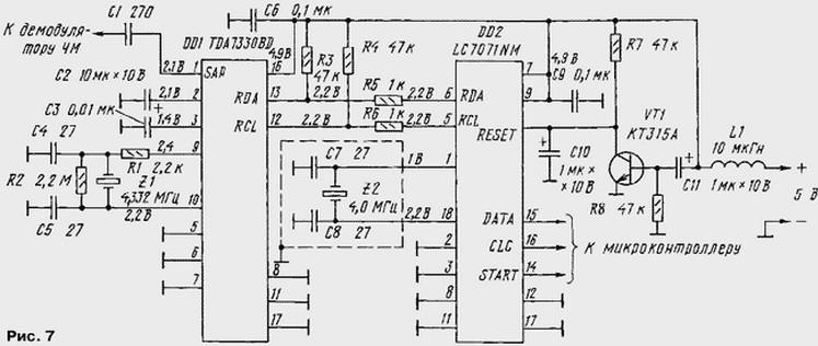
All these microcircuits have no domestic analogues. The most common are TDA7330, LC7071 and LC7073 with different indexes. Using them, you can assemble the RDS block according to the scheme used in the already mentioned "SONY XR-U300 RDS" car radio. The corresponding part of the circuit diagram of this apparatus (it is shown in full on pages 68, 69 in [4]) is shown in Fig. 7. The block consists of a demodulator on the TDA7330BD and a decoder on the LC7071NM chip (can be replaced by a complete analogue of the LC7073MTLM).
At pin 1 of the DD1 chip, the SAP signal is supplied from the output of the FM modulator of the VHF radio receiver. Transistor VT1, when the power is turned on, generates a RESET signal that sets the DD2 chip to its initial state. From pins 14-16 DD2, the output signals DATA, CLC, START are removed, which are transmitted to the receiver microcontroller or directly to the driver. Conclusions DD1 and DD2, not shown in fig. 7, remain free. The circuit is a development of the one shown in Fig. 4, and requires no further explanation. Summing up, we can say that the RDS system in our country is just beginning to show signs of life. The range of element base offered on the market is still insufficient, so the time to create amateur radio designs for RDS devices, apparently, has not yet come. This situation can change dramatically in a very short time - in many European countries, the service capabilities of the RDS system have become a noticeable phenomenon in broadcasting reception technology. Literature
Author: I.Meleshko, Reutov, Moscow region
Artificial leather for touch emulation
15.04.2024 Petgugu Global cat litter
15.04.2024 The attractiveness of caring men
14.04.2024
▪ Audi is phasing out electric vehicles in favor of hybrids ▪ Solar panels over water channels ▪ Seagate Introduces High-Speed Enterprise Turbo SSHD Drives ▪ Windows 8 will ruin this year for Intel
▪ site section Spectacular tricks and their clues. Article selection ▪ article Enough kondrashka. Popular expression ▪ Article What is the longest bridge? Detailed answer ▪ article Forced idle economizer. Personal transport ▪ article Device Perpetual alarm clock. Encyclopedia of radio electronics and electrical engineering ▪ Article Magic trio. Focus Secret
Home page | Library | Articles | Website map | Site Reviews
www.diagram.com.ua |


 Leave your comment on this article: