|
|
ENCYCLOPEDIA OF RADIO ELECTRONICS AND ELECTRICAL ENGINEERING VHF heterodyne receiver at 144 MHz. Encyclopedia of radio electronics and electrical engineering
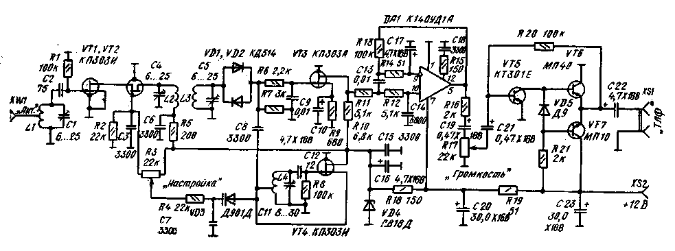
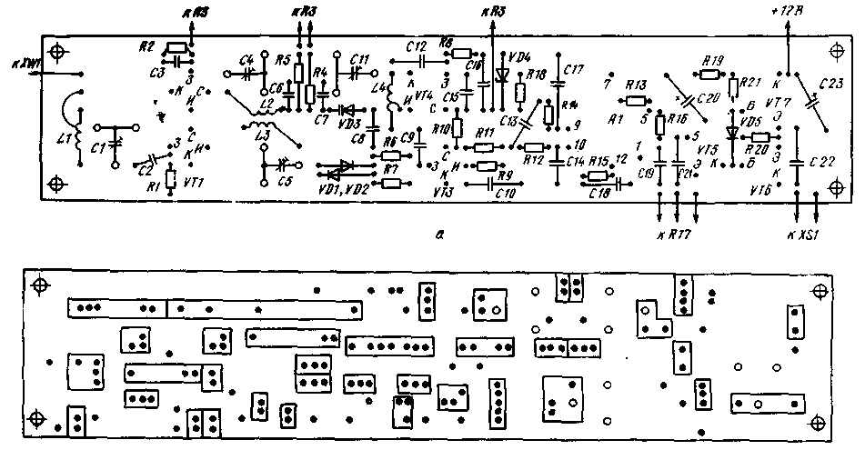
Encyclopedia of radio electronics and electrical engineering / radio reception When developing a heterodyne receiver for the range of 144 ... 146 MHz, it is necessary to take into account the specific features of VHF. The saturation of the range with stations is very small, so the requirements for the selectivity of the receiver can be somewhat reduced. This allows you to use an active filter in the ultrasonic frequency converter and avoid the laborious process of winding low-frequency coils. At the same time, the level of external noise is low, and the station signals are weak, so the receiver sensitivity must be extremely high. URF and UHF with a high gain are needed. A schematic diagram of a receiver for a range of 2 m, designed taking into account the above features, is shown in Fig. 1. The input signal from the antenna through the L1C1 circuit is fed to the URC, assembled according to the cascode circuit on field-effect transistors VTI and VT2. At the URF output, a two-loop bandpass filter L2C4 and L3C5 is included, which significantly attenuates out-of-band interference (signals of television centers, etc.). URF, assembled on field-effect transistors, is highly linear, but has a small gain. To increase the gain, the transistor VT2 can be replaced with a bipolar one, for example, of the GT311 type. If this causes self-excitation, the collector of the transistor should be connected to the tap of the coil L2. The receiver mixer is made on anti-parallel diodes VD1, VD2. The local oscillator, assembled on a VT4 field-effect transistor, is tuned in the range of 72 ... 73 MHz. The VD3 varicap is used for tuning. By changing the connection point of the varicap, you can also change the tuning range from 100 kHz to several megahertz. A low-noise field-effect transistor VT3 is installed in the first stage of the ultrasonic frequency converter. For pre-filtering of sound signals, the R6C9 chain installed in its gate circuit is used. The amplified low-frequency signal is fed to the main amplifier chip DA1. The elements of the active filter at the input of the main amplifier are the chains R11C13 and R12C14. The feedback voltage required for the operation of the active filter is obtained from the output voltage of the amplifier using the divider R13R14. The ratio of the resistors of the divider is approximately equal to the gain of the microcircuit. For direct current, the amplifier is covered by 100% negative feedback, which stabilizes its mode. Further, the amplified and filtered low-frequency signal is fed through the volume control R17 to the final amplifier, assembled in the usual way. It contains a voltage amplifier on a transistor VT5 and a push-pull emitter follower on transistors VT6 and VT7. The receiver is powered by a stabilized rectifier with an output voltage of 12 V. The current consumption in silent mode is 25 mA. In the receiver, transistors and an operational amplifier of the indicated types with any letter indices can be used. The final ultrasonic frequency converter can be assembled on any low-frequency transistors of a suitable structure. The VD4 zener diode is of any type, with a stabilization voltage of 8 ... 9 V. Ceramic capacitors are used in the high-frequency part of the receiver, the remaining capacitors and resistors can be of any type. All tuned capacitors are KPK-M, but it is better to install a C11 capacitor with an air dielectric in the local oscillator. The receiver coils are wound with PEL 0,7 wire. Coils LI, L2 and L3 are frameless, 5 mm in diameter. L1 contains 5 turns with a winding length of 8 mm, and L2 and L3 each have 4 turns, wound turn to turn. The frame of the local oscillator coil L4 is a ceramic tube with a diameter of 5 mm. The wire is wound with high tension and fixed by soldering the ends to the metallized areas of ceramics. You can also fix the wire with BF-2 glue, but the stability of the local oscillator frequency in this case will be worse. The coil contains 6 turns, the tap is made from 1,5 turns, the winding length is 6 mm. The receiver is mounted on a printed circuit board made of foil fiberglass with dimensions of 220x45 mm. The arrangement of parts is shown in fig. 2a. The foil is not removed from the board anywhere, only insulating tracks are cut between its individual sections with a sharp knife or cutter. The track width is 1...2 mm. Such mounting provides the maximum area of "earth" conductors and natural screening between the current-carrying sections, which significantly reduces parasitic coupling and improves the stability of the receiver. It is also possible to apply the installation developed by UW3FL "on points" [6] - round areas with a diameter of 5 ... 7 mm, separated by an insulating path from the rest of the foil serving as a common wire. The parts are soldered with leads to the "points" or to the common wire from the side of the foil. The receiver board is placed on a rugged chassis or, even better, in a closed metal box (enclosure). It is necessary to take care of the mechanical strength of the case and the reliability of all electrical contacts between the parts of the structure, since the stability of the local oscillator frequency depends on this. The conclusions of the resistors R3 and R17, if they are of considerable length, should be carried out with a shielded wire. The installation of the receiver can also be hinged, if you select or make a rectangular box with dimensions close to those indicated. Inside, several shielding partitions should be installed, highlighting the input circuit, mixer and local oscillator. Unlike a HF receiver, by turning on which one can hope to immediately hear at least powerful stations, a VHF receiver needs careful and painstaking adjustment before it "comes to life". First, measure the voltage at the emitters of transistors VT6, VT7 and set it equal to half the supply voltage, selecting resistor R20. Similarly, the voltage is set to 6V at the output of the operational amplifier (pin 5 of the microcircuit), selecting the resistor R9 in the source circuit of the transistor VT3. In the case of self-excitation of the UZCH, when the regulator R17 is set to the maximum volume position, the capacitance of the blocking capacitors C16, C20 and C23 is increased, the conclusions of the potentiometer R17 and the wire going to the XSL output jack are shielded. The noise of the first stage of a normally operating UZCH is heard quite loudly. If there is a sound generator, it is useful to remove the frequency response of the UZCH by connecting the ZG through a voltage divider to the connection point of resistors R6 and R7. The amplifier must have a bandwidth of 0,7 450 ... 2700 Hz. The attenuation of the signal at a frequency of 10 kHz reaches 30 dB. You can adjust the frequency response of the amplifier by selecting the values of capacitors C9, C 13, C 14 and resistor R14. To tune the high-frequency part of the receiver, it is desirable to have a resonant wavemeter, GIR or VHF generator. The local oscillator frequency of 72 ... 73 MHz can be set by receiving its signal to a broadcasting receiver with a VHF band. The local oscillator is heard as a carrier of a powerful station during transmission pauses. The rotor of the capacitor C11, when properly adjusted, is about 3/4 inserted. The RF contours are adjusted to the maximum noise at the receiver output. The rotors of the capacitors of these circuits are introduced by about 1/3. Contour tuning is quite sharp. The contours can be adjusted more precisely to the maximum of any signal with a frequency of 144 MHz applied to the input of the receiver. In the absence of a VHF generator, you can take the harmonic of the simplest home-made quartz oscillator operating at a frequency of 8, 9, 12, 18, etc. MHz. The fifth harmonic of generators operating at a frequency of 10-meter range of 28,8 MHz is well heard. After tuning, the receiver is calibrated using a quartz calibrator. The scale is conveniently made in the form of a disk mounted on the axis of the tuning potentiometer. The tuned receiver has a high sensitivity. When connecting an external 2-meter antenna, the noise increases noticeably due to "air noise" even in the absence of industrial interference. The disadvantage of the receiver is the low frequency stability of the local oscillator, because of this, when receiving SSB stations, it often has to be adjusted. Telegraph stations are received much better, their tone is quite clear. However, with large changes in temperature and supply voltage, the local oscillator frequency drift can reach tens of kilohertz. Therefore, to periodically check the calibration of the scale, it is useful to have a reference signal with a known frequency obtained from a quartz calibrator or a simple quartz local oscillator. The master oscillator of a telegraph transmitter with quartz frequency stabilization can successfully serve as a reference oscillator. If the transmitter already has a tunable oscillator, its signal can be fed to the receiver mixer, thus building a direct conversion transceiver. Transistor VT4 and varicap VD3 are not installed in this case, and the L4C11 circuit is connected to the intermediate stage of the transmitter, tuned to a frequency of 72 MHz. A tunable master oscillator can be built according to a crystal oscillator circuit with frequency shifting by external elements connected to the resonator (VXO) or according to a circuit with biased quartz and smooth local oscillator signals. When operating the receiver as part of a radio station, care must be taken to protect the RF transistors from the powerful signal of its own transmitter. It is advisable to use an antenna relay with a low contact capacity. To limit the leaked signal, it is useful to shunt the L1C1 circuit with a pair of anti-parallel silicon diodes, for example, of the KD503 type. and is powered by a 4V battery. Author: V.T.Polyakov, Moscow; Publication: N. Bolshakov, rf.atnn.ru
Artificial leather for touch emulation
15.04.2024 Petgugu Global cat litter
15.04.2024 The attractiveness of caring men
14.04.2024
▪ The brain can block the storage of certain memories
▪ section of the site Funny puzzles. Article selection ▪ article Theory and methods of education. Lecture notes ▪ article Which animals are the fastest? Detailed answer ▪ article Dispatcher. Standard instruction on labor protection ▪ article Rain noise simulator. Encyclopedia of radio electronics and electrical engineering
Home page | Library | Articles | Website map | Site Reviews www.diagram.com.ua |


 Arabic
 Bengali
 Chinese
 English
 French
 German
 Hebrew
 Hindi
Hindi Italian
 Japanese
 Korean
 Malay
Malay Polish
 Portuguese
 Spanish
 Turkish
 Ukrainian
 Vietnamese


 Leave your comment on this article: