|
|
ENCYCLOPEDIA OF RADIO ELECTRONICS AND ELECTRICAL ENGINEERING Power supply for a radio amateur 0-30 volts. Encyclopedia of radio electronics and electrical engineering
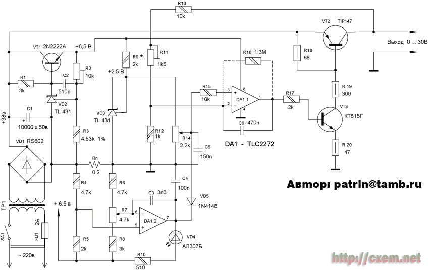
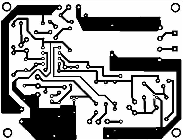
Encyclopedia of radio electronics and electrical engineering / Power Supplies The development of a power supply for a home laboratory is presented to the attention of radio amateurs. The advantage of this PSU is that no additional windings are needed on the power transformer. Chip DA1 works with unipolar power supply. The output voltage is continuously adjustable from 0 to 30 V. The power supply has a continuously adjustable current limit. The circuit solution is simple and this power supply can be made by a beginner radio amateur. The rectified voltage +38 V, after the capacitor C1, is supplied to the regulating transistor VT2 and the transistor VT1. A stabilizer is assembled on the transistor VT1, diode VD2, capacitor C2 and resistors R1, R2, R3, which is used to power the DA1 chip. Diode VD2 is a three-pin, adjustable, parallel voltage regulator. [2] At the output of the stabilizer, resistor R2 sets a voltage of +6,5 volts, since the limiting supply voltage of the DA1 microcircuit VDD = 8 volts. On the operational amplifier DA1.1 TLC2272 [ 1 ], the regulating part of the voltage of the power supply is assembled. Resistor R14 regulates the output voltage of the power supply. A reference voltage of 14 volts is applied to one of the contacts of the resistor R2,5. The accuracy of this voltage, within small limits, is set by selecting the resistor R9. Through the resistor R15, regulated by the resistor R14, the voltage is applied to the input 3 of the operational amplifier DA1.1. Through this operational amplifier, the output voltage of the power supply is processed. Resistor R11 regulates the upper limit of the output voltage. As already mentioned, the DA1 chip is powered by a unipolar voltage of 6,5 V. And, nevertheless, it was possible to obtain an output voltage of 0 V at the output of the power supply. On the DA1.2 chip, a current and short circuit protection unit is built. Such circuit solutions for protection nodes have been described in various RL literature and therefore are not considered in detail. In the author's version, the current can be adjusted from 0 to 3A. The R10 and VD4 chain is used as an indicator of overcurrent and short circuit. The schematic diagram of the power supply is shown in fig. one. The establishment of the power supply begins with a voltage supply of + 37 ... 38 V. To the capacitor C1. With the help of resistor R2, a voltage of + 1V is set on the collector VT6,5. Chip DA1 is not inserted into the socket. After the output voltage on leg 8 of the DA1 socket is set to +6,5V, the power is turned off and the microcircuit is inserted into the socket. After that, the power is turned on and, if the voltage on pin 8 DA1 differs from + 6,5V, it is adjusted. Resistor R14 must be driven to 0, i.e. to the bottom position. After the supply voltage of the microcircuit is set, a reference voltage of +2,5V is set at the upper terminal of the variable resistor R14. If it differs from that indicated in the circuit, select the resistor R9. After that, the resistor R14 is moved to the upper position and the trimmer resistor R11 sets the upper limit of the output voltage + 30V. The output lower voltage without resistor R16 is 3,3 mV, which does not affect the reading of the digital indicator and the readings are 0V. If a 1 MΩ resistor is included between legs 2 and 1.1 of the DA1,3 microcircuit, then the lower limit of the output voltage will decrease to 0,3 mV. Contact pads for resistor R16 are provided in the printed circuit board. Then the rheostatic resistance is connected to the load and the parameters of the protection node are checked. If necessary, select resistors R6 and R8. The following components can be used in this design. VD2, VD3 - KPU2EH19, instead of the transistor VT2 TIP147, you can use the domestic transistor KT825, VT3 - BD139, BD140, VT1 - any silicon low or medium power transistor with a voltage Uk of at least 50V. Trimmer resistors R2 and R11 from the SP5 series. The power transformer can be used for a power of 100 ... 160W. Resistor R16 with a TC characteristic of at least 30 ppm / Co and must be either wire or metal-foil type. The power supply is assembled on a printed circuit board measuring 85 x 65 mm.
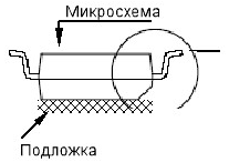
The reference voltage node on VD3 can be replaced by a node on the TLE2425 chip - 2,5 V. [3] The input voltage of this microcircuit can vary from 4 to 40 V. The output voltage is stable - 2.5 V. During setup, instead of the TLC2272 chip, the TLC2262 chip was experimentally used. All parameters remained equal to the specified ones, no mode deviations were observed. When testing this design, the microcircuit was powered not by 6,5 V, but by 5 V. In this case, the resistor R9 \u1,6d 5K. The microcircuit power node has been replaced by the node shown in fig. XNUMX. If the TLC2272 chip is not in the DIP-8 package, but in SOIC-8, then you can do the following without reworking the printed circuit board. A substrate is prepared from the isolated material - a rectangle, 20 x 5 mm in size. On this rectangle, with "MOMENT" glue, it is glued "with paws to the top", i.e. upside down, microchip. The location of the chip on the substrate is shown in Fig. 6. After that, the resulting "sandwich" is glued, with the same glue, on the reverse side of the printed circuit board, after removing the DIP-8 socket (if it was soldered). The substrate with the microcircuit is glued, positioned evenly between the contact pads of the microcircuit on the printed circuit board. Leg 1 of the microcircuit should be opposite the contact pad belonging to leg 1 of the DA1 microcircuit, or shifted slightly lower. After this operation, using flexible conductors and a soldering iron, we connect the legs of the microcircuit and the pads on the printed circuit board. Radio amateurs collected several copies of these power supplies. All of them started working immediately and showed the desired results.
When developing the design, an inexpensive base of parts, a minimum of parts, ease of setup and handling, as well as output parameters that are most acceptable among radio amateurs, were taken into account.
Literature [1] radiodetail.narod.ru/m_i/m_i_tl/tlc2272.htm
Publication: cxem.net
Machine for thinning flowers in gardens
02.05.2024 Advanced Infrared Microscope
02.05.2024 Air trap for insects
01.05.2024
▪ Getting energy from carbon dioxide ▪ Samsung Wireless: 1,5TB wireless storage, hotspot, offline charging ▪ New technology to keep food fresh in the refrigerator
▪ section of the site For a beginner radio amateur. Article selection ▪ Article Young Guard. Popular expression ▪ article In what country were children forced to portray grazing sheep? Detailed answer ▪ Article Head of Public Relations Department. Job description ▪ article Antenna Mini square. Encyclopedia of radio electronics and electrical engineering
Comments on the article: Alexander Is it possible to replace the op-amp with an LM358 in this circuit a guest Is there any other discussion of this bp on the forum? Gennady Is it possible to double the output current in this circuit by paralleling two output transistors? a guest Content stimulates clarity of presentation on the topic [;)] Alexander In the circuit, the current is not regulated, I collected it and I don’t believe that someone collected it and everything worked right away. So they made improvements that are not written anywhere, if anyone knows, write I will be grateful. For proof of my assembly of the block, see the YouTube channel. Alexander. Radio repair and homemade, as well as a lot of other assembled devices and repairs on the channel, more than 500 videos.
Home page | Library | Articles | Website map | Site Reviews www.diagram.com.ua |


 Arabic
 Bengali
 Chinese
 English
 French
 German
 Hebrew
 Hindi
Hindi Italian
 Japanese
 Korean
 Malay
Malay Polish
 Portuguese
 Spanish
 Turkish
 Ukrainian
 Vietnamese


 Leave your comment on this article: