|
|
Chip TDA8362 in 3USCT and other TVs. Part 4. Encyclopedia of radio electronics and electrical engineering
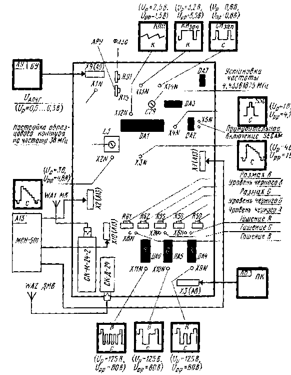
Encyclopedia of radio electronics and electrical engineering / Телевидение Now turn on the TV. A raster should appear on the screen, but without a picture, since the antenna and control circuits are disconnected from the radio channel. Power is supplied to the MRCC, and this allows you to check its performance. The appearance of a raster means that there are no serious malfunctions in the MRCC. Check the supply voltages +220, +12, +8, +5,6 V and at the microcircuit pins. Noticing that they differ from those indicated in the diagrams by more than 10 ... 15%, check the correct installation of the corresponding circuits. In televisions with UVP types SVP, USU, noise should appear in the loudspeaker, and if the exemplary circuit is not too detuned, the sound accompaniment of the previously configured program should also appear. There will be no noise on a TV with MCH - until the exemplary circuit is tuned, the SOS signal is not generated and the silent tuning system closes the sound path. If all the voltages are within the normal range, make (by turning off the TV) the changes shown in fig. 7, connect cables Х5 (А9), ХЗ (А8), Х7 (А13), Х10 (А13) to MRCC. Cable X5 (A3) should not be switched on yet. It is necessary to turn on the TV, make sure there is a raster and, if it is absent, check the performance of the brightness and contrast controls, the health of the brightness control circuit. When you get a screen glow, check for noise or an out of sync image. After that, remove the plug with resistors R10, R5 from pin 3 of connector X301 (A302) and turn on connector X5 (A3) in the PSP, which will transfer the horizontal and vertical scanning units to control from the MRKTs (before that they were controlled by signals from the USR and MRK module) . Make changes (by turning off the TV) in the PSP (A3) according to fig. 9. After that, turn on the TV and check for the presence of a raster. Set up a model outline. If you have a high frequency generator, follow the recommendations in [2]. There is no such generator - tune the L3 coil based on the assumption that the exemplary circuit in the removed RTO was previously correctly tuned to a frequency of 38 MHz, and the UVP presetting system accurately generated voltage for the channel selectors and they were tuned to the carrier signals of television transmitters . Then, without changing the adjustment of the UVP and not turning on the APCG system, it is necessary to tune the exemplary MRCC circuit to the same frequency to which a similar circuit was tuned in the MRCC. To do this, connect a DC voltmeter to the X1N point of the MRCC and adjust the L3 coil to a voltage of +3,5 V at the indicated point. When using SVP, USU, the setting of the exemplary circuit is completed. When using an MSN resistor R22 (see Fig. 2) in the MSN, set the voltage to +2,5 V at point XN3 in the module. Adjusting the reference contour should result in sound and a synchronized image. Check with an oscilloscope the conformity of the shape and amplitude of the signals at all control points, for which in fig. 16 shows their appearance in the case of receiving vertical color bars (Up is the constant component of the signal, Upp is the signal amplitude). If there is no signal at any point, look for the cause using the considered diagrams and description. With variable resistors USU or SVP (module tuning system MCH) achieve the highest clarity of reception of the test table. Set the AGC level so that there is no noise and vertical line distortion on all received programs. Adjust the size, linearity and centering of the frames with the construction resistors of the MK-1-1 module and the phase with the MRCC resistor.
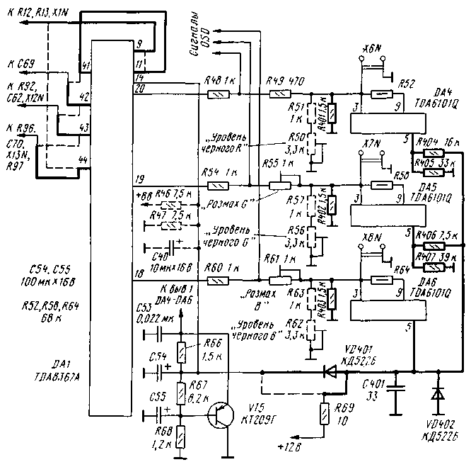
Achieve white balance. In the position of the brightness control at the minimum level, with resistors R50, R56, R62, set the voltage level to 9 + 11 V at the control points X125N-X5N. Then, when using kinescopes 61LKZTs, 61LK-4Ts, by adjusting the resistors R3, R5, R7 in the accelerating voltage circuits, get the white balance at the minimum brightness level. If this fails (the modernized TV has a kinescope with degraded cathode emission), you can achieve white balance at this brightness level by adjusting the resistors R50, R56, R62 for any type of kinescope. Then increase the brightness to a normal level and by adjusting the resistors R55, R61 first set the range of the signals at points X10N, X11N equal to the range of "red" at point X9N. Next, you need to adjust these resistors until the white balance is at the level of normal brightness. Repeat the adjustment several times until the white balance is maintained at any brightness level. Check the focusing of each of the kinescope beams separately, if necessary, it can be improved by adjusting the corresponding resistor on the kinescope board (only for 61LKZTs / 4Ts), and then check and adjust the white balance. The next step is to adjust the beam current limiting system. To do this, you need to connect a voltmeter to pin 25 of the DA1 MRCC chip and set the tuning resistor R20 in the line scan module to a position at which the voltmeter readings begin to decrease. Check the operation of the MRCC from external sources of video information. Disconnect the X4 plug (A3) of the MRCC from the setup cable and plug it into the PSP (A3). Remove the MRK and MC modules from the TV chassis, install the MRKTs on it and finally check it. If you encounter any difficulties while setting up the module, refer to section 3.2.3 of the manual [7], where possible malfunctions and ways to eliminate them are indicated. Using the TDA8362A chip instead of the TDA8362 allows you to enter into the module the function of automatically setting the dark currents of the kinescope (automatic white balance - ABB). The changes that need to be made for this in the previously considered schemes are shown in Fig. 17. They are related to the differences in the pinout of microcircuits and the introduction of ABB. To correct the differences in the pinouts, you need to remove the conductor connecting pins 9 and 11 of the DA1 microcircuit, and connect pins 11 and 41 (the removed circuits are shown in Fig. 17 with a dashed line, and the newly introduced circuits are thickened). The APCG circuit that connected the elements R12, R13, X1N with pin 44 is connected to pin 9 of the microcircuit. Switch the KIzap circuit from the connection point of the elements C70, R96, R97, X13N from terminal 43 to terminal 44. Reconnect the frame saw generator circuit from the elements C62, R92, X12N from terminal 42 to terminal 43, and the personnel OOS circuit from capacitor C69 and contact 10 connector X5 (A3) connect to terminal 42. To introduce ABB, you need to change the signal supply circuits R, G, B from the DA1 chip to DA4-DA6 and organize the transfer of measuring pulses from the ABB sensors to pin 14 of the DA1 chip (they are output to pins 5 of the DA4-DA6 chips). In the circuits for passing signals from pins 18-20 of the DA1 microcircuit to the pins of 3 amplifiers DA4-DA6, the black level setting resistors R50, R56, R62 are excluded, and instead of the resistors R51, R57, R63, R401-R403 are installed. Signal chain ABB includes elements R404-R407, VD401, VD402, C401. Resistor R69 from the connection point of the elements R66, R67, C54 (see Fig. 6) is switched to the connection point of the elements VD401, VD402. C401, R404, R406. From pin 11 of the DA1 chip, disconnect (as unnecessary) resistors R46, R47 and capacitor C40. Resistors R404-R407 are installed near the DA5, DA6 microcircuits, where a place is provided for them on the board. Parts C401, VD401, VD402 are placed in the free space between the DA6 chip and the SK-D-24 selector. Adjusting the ABB system in this case is simpler than a similar procedure when using the TDA8362 chip. The white balance at minimum brightness (dark level) is set automatically by the ABB system. White balance at optimal brightness (at the light level) is adjusted by trimmers R55 "Span G" and R61 "Span B". It is necessary to explain a little the economic side of the proposed alteration. The module will cost about 110 rubles. (TDA8362 - 35 rubles, TDA8395 - 18 rubles, TDA4661 - 14 rubles, TDA6101Q - 5 rubles, as well as transistors, capacitors and resistors - 30 rubles) at the prices of the CHIP and DIP store (spring 1998). To purchase a more modern channel selector, you need to spend 50 ... 80 rubles. Replacing a push-button UVP with a voltage synthesizer requires about another 110 rubles. (MSN-501, standby reception unit BPD-45, remote control PDU-5). Consequently, the alteration will cost 110 ... 300 rubles. depending on the degree of refinement. And what will be the result? 1. Increasing the sensitivity of the TV and effective noise suppression for weak signals, high-resistance interlacing. 2. Multi-standard and multi-system operation (SECAM-BG / DK, PAL-BG / DK), and if necessary, NTSC-4,43. 3. Increasing the reliability of work by reducing the number of components used, inter-module connections, adjustment elements. 4. Protecting the kinescope from burning through. 5. Reducing (though not very large) power consumption. 6. When installing a voltage synthesizer, the TV will acquire all the functions characteristic of fifth generation devices. In conclusion, we note that a new modern television of the fifth and sixth generations, which has a kinescope with a diagonal size of 53 cm, cost 2.5 ... 3 thousand rubles (until August of this year). Literature
Author: V. Brylov, Moscow; Publication: N. Bolshakov, rf.atnn.ru
Alcohol content of warm beer
07.05.2024 Major risk factor for gambling addiction
07.05.2024 Traffic noise delays the growth of chicks
06.05.2024
▪ Purification of drinking water from drugs ▪ Solectrac e70N electric tractor
▪ site section Power supply. Article selection ▪ article Car tire for a summer shower. Tips for the home master ▪ article Why are London cops called bobbies? Detailed answer ▪ article Bouquet from a tube. Focus secret
Home page | Library | Articles | Website map | Site Reviews www.diagram.com.ua |


 Arabic
 Bengali
 Chinese
 English
 French
 German
 Hebrew
 Hindi
Hindi Italian
 Japanese
 Korean
 Malay
Malay Polish
 Portuguese
 Spanish
 Turkish
 Ukrainian
 Vietnamese


 Leave your comment on this article: