|
|


 Arabic
 Bengali
 Chinese
 English
 French
 German
 Hebrew
 Hindi
Hindi Italian
 Japanese
 Korean
 Malay
Malay Polish
 Portuguese
 Spanish
 Turkish
 Ukrainian
 Vietnamese
|
ENCYCLOPEDIA OF RADIO ELECTRONICS AND ELECTRICAL ENGINEERING Remote control of lighting. Encyclopedia of radio electronics and electrical engineering
Encyclopedia of radio electronics and electrical engineering / Lighting If an apartment, a rural house, a country house has a long corridor, utility rooms with two exits, etc., then in order to save electricity and ease of use, it is advisable to be able to turn the lighting on and off in them from different places. A diagram of a device that implements such a function is shown in Fig. 1.
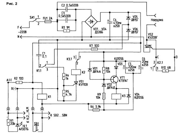
The device uses a polarized on-off relay of the RP4 type (passport RS4.520.009, RS4.520.012), however, relays with other passports that have windings with a resistance of 300 to 2000 ohms are also suitable. To turn on the lighting, the SB1 button is briefly pressed (parallel to it, you can turn on a group of buttons). In this case, the alternating voltage (3 V) released on the resistor R10 is rectified by the diode VD2 and "transfers" the armature of the relay K1 to the right contact, closing the control circuit of the triac VS1. The triac opens and supplies voltage to the load - the lighting lamp. When the SB2 button is pressed, a voltage of the opposite polarity, rectified by the VD1 diode, is applied to the relay winding K3, and the relay armature switches to the left contact. The triac control circuit breaks, it closes, and the light goes out. To find the buttons in the dark, HL1 ... HLM LEDs (with their own quenching resistors similar to R2) are introduced into the circuit, installed near the buttons and operating in light mode at a current of 1 mA. It is advisable to connect the phase and neutral wires of the network to the device as indicated in the diagram. Then the buttons will have a safe voltage (relative to the grounded neutral). When the mains voltage disappears and it reappears, the device remains in the same state it was in before it was turned off. Triac VS1 is equipped with a heat sink with an area of about 10 cm2, which allows you to switch loads up to 400 W. The power consumption of the device itself is 0,5 W. To turn the device on and off, you can get by with one control button (parallel connected group), but, of course, the circuit becomes more complicated (Fig. 2).
If you need to turn on the lighting, briefly press the button SB1 (the duration of pressing is no more than 1 s), and if you turn it off, press the button for 2 ... 3 seconds. When the button is pressed for 1 s, only relay K1 is activated, and when it is pressed for 2 ... 3 s, relays K1 (switching on) and K3 (switching off). When K1 is triggered, contacts K 1.1 (from 21 to 23) are switched, charged to a voltage of 10 V capacitor, connected to the control electrode of the thyristor VS1 and opens it. This creates a circuit for actuating relay K2 (through the normally closed contacts K3.1 of the short circuit relay), which closes the circuit of the control electrode of the triac VS2.1 with its contacts K2. The triac, opening, turns on the lighting lamp. If you hold the button pressed for 2-3 s (more than 3 s is possible), then the K1 relay is also activated, but the state of the thyristor VS1 does not change (it is already open). Capacitors C5, Sat are charged through a closed button. After 2 s, the voltage across the capacitors is sufficient to breakdown the Zener diode VD2. Then the transistor VT1 opens, and the short-circuit relay is activated for a short time. Breaking the anode circuit of the thyristor VS3.1 with its contacts K1. It closes, relay K2 releases pressing the button to turn off the lighting depends on the total containers C5 and C8. When the mains voltage disappears and reappears, the circuit will be in a state in which the lighting is turned off. It is desirable to connect the phase and neutral wires of the network to the device in this way. as indicated in the diagram (Fig. 2), so that the buttons have a safe voltage (relative to the neutral). Both devices have a galvanic connection to the network, therefore, when setting them up, appropriate safety measures must be observed. During commissioning, it is better to power the second circuit with a voltage of 25 V from a laboratory source (connected to points A and 8). To control the triac start circuit, an ohmmeter is connected to points C and D. In fact, the circuit is powered by a voltage of 20 V due to VD5 zener diodes. VD6 connected in series. The device uses reed relays of the RES55A type (passport 0001) with a winding resistance of 1800 ohms, the thyristors KU110V can be replaced with KU110A, and with its contacts K2.1 it breaks the control circuit of the triac VS2. The triac closes and turns off the corridor lighting. LEDs HL1...HLM (with their damping resistors) indicate the location of the buttons in the dark. Permissible load of the device - 400 W, power consumption in standby mode - about 2 W Zener diodes VD5. VD6 are equipped with body taps with an area of 8 cm2, and triac VS1 - approximately 10 cm2. The device is assembled in a plastic case measuring 80x230x40 mm. Author: D.S.Babyn, village of Kelmentsy, Chernivtsi region.
Air trap for insects
01.05.2024 The threat of space debris to the Earth's magnetic field
01.05.2024 Solidification of bulk substances
30.04.2024
▪ Transforming Drone from Samsung ▪ Light bulb with vacuum cleaner ▪ The size and shape of the human nose determined by the climate ▪ Graphene may help fight cancer
▪ site section Electric meters. Article selection ▪ article Ways to improve the efficiency of human labor activity. Basics of safe life ▪ article What is the difference between an underground spring and an artesian well? Detailed answer ▪ article Insulation and roofing works. Standard instruction on labor protection ▪ article Spoon in a paper tube. Focus Secret
Home page | Library | Articles | Website map | Site Reviews
www.diagram.com.ua |


 Leave your comment on this article: