|
|


 Arabic
 Bengali
 Chinese
 English
 French
 German
 Hebrew
 Hindi
Hindi Italian
 Japanese
 Korean
 Malay
Malay Polish
 Portuguese
 Spanish
 Turkish
 Ukrainian
 Vietnamese
|
ENCYCLOPEDIA OF RADIO ELECTRONICS AND ELECTRICAL ENGINEERING Improving the sound of 35AC-1 and its modifications. Encyclopedia of radio electronics and electrical engineering
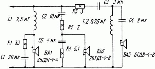
Encyclopedia of radio electronics and electrical engineering / Speakers The three-way speaker system 35AC-1, developed at the Orbita design bureau of the Riga production association Radiotekhnika, can be called without exaggeration the founder of the speaker family, which made high-quality sound reproduction a reality at home. At that time, 35AC-1 was the best not only among domestic household loudspeakers, it sounded better than many speakers from foreign companies. In 1979, on the basis of 35AC-1 (the crossover filter and the front panel of acoustic design underwent changes), 35AC-212 (S-90) was created, which is currently produced by several enterprises under the names 35AC-012 and 35AC-016. Unfortunately, today these speakers no longer satisfy the increased demands of lovers of high-quality sound. As studies conducted at the Department of Broadcasting and Electroacoustics of the Moscow Electrotechnical Institute of Communications (MEIS) showed, the weakest link in AC is the mid-frequency dynamic head 15GD-11 A. The frequency response of this head has a sharp drop above 4,5 kHz, which practically excludes the possibility of obtaining "bright", "transparent" sound in the mid-range. It also has another drawback - a large mass of the moving system, which, however, can be successfully dealt with by introducing acoustic damping [1]. The high-frequency head 10GD-35 is not without flaws. The main one is the high resonance frequency of the moving system. A crossover filter with a cutoff frequency of 5 kHz is not able to attenuate signal components whose frequency coincides with the resonant one, and this generates a lot of unpleasant overtones. It is possible to significantly improve the sound quality of the speakers by eliminating the causes that worsen it, i.e., replacing the 15GD-11A head with a 5GDSH-5-4 broadband head (the former designation is 4GD-53) and increasing the crossover frequency of the mid- and high-frequency bands from 5 to 10 kHz. After such a refinement, the nameplate power of the speaker is reduced by about half, so it can only be operated with an amplifier whose rated output power does not exceed 50 W (per channel). However, as practice shows, this is quite enough to obtain high-quality sound reproduction in any living room. The choice of the 5GDSh-5-4 broadband head is not least due to the identity of its mounting dimensions with the 15GD-11A head, which facilitates replacement and allows you to keep the appearance of the speaker intact. To improve the parameters of the 5GDSh-5-4 head, it is necessary to smear a part of the upper suspension of the diffuser with non-drying vibration-absorbing mastic [2] and provide it with an acoustic resistance panel by sealing the windows of the diffuser holder with synthetic felt (TU 17-35-3941-81) or other suitable material [1]. Let's consider the refinement procedure using the 35AC-016 system as an example. Putting it with the back wall down, unscrew the screws, remove the decorative trims, remove the heads 15GD-11A n 30GD-1 and through the hole for the latter - the separation filter board. Since the thickness of the diffuser holder flange of the new head is much thinner, it is necessary to place an annular gasket under it, cut exactly to the dimensions of the flange from porous rubber with a thickness of 8 ... 10 mm. To avoid touching the diffuser and the protective grid on the screws (between the head and the decorative trim), put on M5 nuts - they will firmly press the head to the mid-frequency head box and, in addition, prevent the deformation of the overlays under the action of the screws. Connect the head 5GDSH-5-4 in the same polarity as 15GD-11A. To equalize the sensitivity and match the 5GDSh-5-4 head with a separation filter (Fig. 1), a resistor R' is connected in series with it (shown in dashed lines in the diagram), which is fixed on the filter board.
Changes in the filter are reduced to the following (item designations of elements, the values of which change during revision, are provided with strokes). Having unsoldered the conclusions of the L4 coil (0,56 mH), it is removed, and the L1 coil (0,22 mH) is installed in the vacated place, which is included in the filter instead of L4 (this increases the upper limit of the operating frequency band of the mid-frequency head). Then 4 turns are unwound from the L115 coil (the new inductance is 0,1 mH) and, having installed it on the board, is connected instead of the L1 coil. Capacitor C1 (2 μF) is replaced by capacitor C2 (1 μF), and instead of the latter, a paper capacitor with a capacity of 0,5 μF is included. After such alteration, the cutoff frequency of the high-frequency section of the filter rises to 10 kHz. To evaluate the effectiveness of the proposed improvement, it is recommended to first remake one speaker and compare its sound with the unmodified one in mono mode. The assessment will be more objective if the listeners do not know which speaker system has undergone modernization, and determine it by the sound preference. It is necessary to switch speakers quickly (for example, using a toggle switch), and it is advisable to do this several times while listening to the same piece of music. The frequency characteristics of the speakers before (dashed line) and after alteration (solid line) are shown in Fig. 2. As you can see, the result of the refinement is manifested in a certain decrease (from K) to (1 dB) in the unevenness of the characteristic in the midrange. Comparative listening showed a confidently noticeable preference for the sound of a converted speaker.
In conclusion, a few words about the refinement of other modifications of this speaker. Schematic diagrams of their crossover filters differ from those shown in Fig. 1 basically only with the ratings and numbering of the elements, So the inductor L4 corresponds to the coil L1 (0,43 mH) in 35AC-212 and L4 (0,55 mH) in 35AC-012 and 35AC-1: coil L1-L4 (0,22 mH) in 35AC-212, L2 (0,23 mH) in 35AC-012 and L1 in 35AC-1. Capacitor C1 in fig. 1 corresponds to capacitor C2 (2 μF) in 35AC-212, C1 (2 μF) in 35AC-012 and C1 (1 μF) in 35AC-1; capacitor C2-C8 (1 uF) in 35AC-212 and 35AC-012. In the 35AC-1 crossover filter, there is no capacitor that performs the function of C2. therefore, when finalizing this speaker, a 10 μF capacitor must be included in the 35GD-0,5 head circuit (into the break in the wire going to the switch). References:
Author: S.Klimberg
Artificial leather for touch emulation
15.04.2024 Petgugu Global cat litter
15.04.2024 The attractiveness of caring men
14.04.2024
▪ Stuffcool Snap Lightning Power Bank for Apple ▪ A new way to control smart watches ▪ Standard supporting 8K VESA Embedded DisplayPort 1.4a ▪ Logitech G633 Headphones with Sound Processor
▪ section of the site Dosimeters. Selection of articles ▪ article Failed, my friend, prophecies. Popular expression ▪ article What kind of mosquito repellant do South American capuchin monkeys use? Detailed answer ▪ article Work on a circular machine. Standard instruction on labor protection ▪ article Automatic water pump control. Encyclopedia of radio electronics and electrical engineering
Home page | Library | Articles | Website map | Site Reviews
www.diagram.com.ua |

 Leave your comment on this article: