|
|


 Arabic
 Bengali
 Chinese
 English
 French
 German
 Hebrew
 Hindi
Hindi Italian
 Japanese
 Korean
 Malay
Malay Polish
 Portuguese
 Spanish
 Turkish
 Ukrainian
 Vietnamese
|
ENCYCLOPEDIA OF RADIO ELECTRONICS AND ELECTRICAL ENGINEERING January-4 The control system of the 8V engine VAZ-2111 of the car VAZ-21093-20
Encyclopedia of radio electronics and electrical engineering / Automobile. Electronic fuel injection The engine control system consists of a distributed fuel supply control subsystem (fuel injection) and an ignition control subsystem. Both subsystems are controlled by email. control unit (controller) and ensure engine performance.
The system includes (see Fig.1) fuel tank, el. fuel pump, fuel pump relay, fuel filter, fuel distributor (battery), mech. fuel pressure regulator, injectors (one for each engine cylinder), mass air flow sensor (DMRV), throttle position sensor (TPS), feedback potentiometer (CO-potentiometer), knock sensor (DD), coolant temperature sensor ( DTOZH), vehicle speed sensor (DSA), crankshaft position sensor (DPKV), el. control unit, ignition module, battery, ignition lock, CHECK ENGINE control lamp, engine cooling system fan (VCO), idle speed controller (IAC) and may include an adsorber, immobilizer, air conditioner.
Structural diagram of the control system
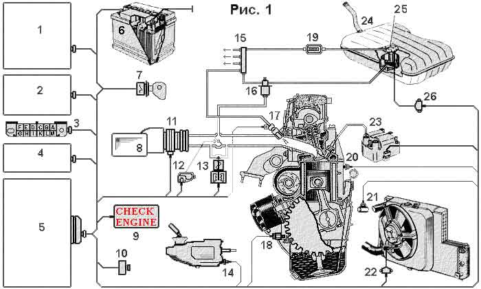 1. Air conditioner module
2. Immobilizer
3. Diagnostic connector
4. Main relay
5. Controller
6. Battery
7. Egnition lock
8. Air filter
9. CHECK ENGINE lamp
10. CO potentiometer
11. Air mass meter
19. Fuel filter
20. Knock sensor
22. Fan enable relay
23. Ignition module
24. Fuel tank
25. Fuel pump
26. Fuel pump relay
The fuel management subsystem functions as follows:
Fuel email the pump (through the fuel filter) supplies fuel from the fuel tank to the fuel rail (distributor) on which the fuel pressure regulator supplied to the injectors is installed. The membrane fuel pressure regulator sets the pressure level in the system to about 300 MPa and returns excess fuel to the fuel tank through the fuel return line. In addition, the fuel pressure in the system depends on the vacuum in the intake tract, which is connected to the pressure regulator. The diaphragm of the bypass valve of the fuel pressure regulator is affected by fuel pressure on one side, and spring pressure and intake air pressure on the other. This ensures optimum fuel pressure in the system in direct proportion to throttle position and engine load.
The fuel injectors are controlled by the controller and provide simultaneous fuel supply to the intake manifold of each engine cylinder with each revolution of the crankshaft. The amount of fuel entering the combustion chambers is proportional to the opening time of the injectors. The controller, in turn, regulates this time by determining it from the signals of sensors installed on the engine. The controller determines the moment when the control signal is applied to the injectors by the signal from the crankshaft position sensor.
In the engine start mode, the controller switches to the asynchronous injector control mode until the engine speed reaches 400 rpm.
The fuel supply to the combustion chambers stops in the engine purge mode (the throttle valve is open by more than 75%, and the rotation of the crankshaft is less than 400 rpm) and may stop briefly in the engine braking mode, depending on the temperature of the coolant, frequency crankshaft rotation, vehicle speed and throttle opening angle.
The controller enriches the fuel mixture in the modes of increased engine load and acceleration by increasing the opening time of the injectors, regulating it according to the signals of the throttle position sensor and the mass air flow sensor, taking into account the speed of the vehicle, according to the signals of the speed sensor.
The electronic control unit controls the supply voltage in the vehicle's on-board network and, if it drops significantly, increases the injector opening time, compensating (due to low supply voltage) the slow activation of the electromechanical injector valves.
In all engine operating modes, based on the signals from the throttle position and mass air flow sensors, the controller determines the amount of air entering the engine and regulates the fuel supply by the injectors to provide the required composition of the fuel mixture. When warming up a cold engine and idling, the controller controls the operation of the idle speed controller and, depending on the load and engine temperature, ensures the crankshaft speed at the required level. When the throttle is quickly closed while the vehicle is moving, the controller increases the air supply by the idle speed control. Thus, the fuel mixture is leaner to ensure a reduction in exhaust emissions.
The ignition is controlled by the controller based on signals from the crankshaft position sensor and taking into account the current mode of engine operation based on signals from other sensors.
The electronic control unit (controller) is a microprocessor system with a non-volatile read-only memory (ROM), a non-volatile reprogrammable memory (PROM) and a random access memory (RAM) that stores data only when the supply voltage is present. The data ROM stores the program of the microprocessor and tables of engine parameters. The microprocessor uses RAM to store intermediate values. The controller controls the fuel injection actuators (ignition, injectors, etc.) and, in addition, diagnoses the operation of the sensors. When a malfunction is detected, the controller lights the CHECK ENGINE lamp and stores an error code in RAM, which can be read by the multitester or indicated by the CHECK ENGINE lamp in diagnostic code scan mode.
Element connection diagram
 1. Spark plugs
2. Ignition module
3. Battery
4. Egnition lock
5. Main relay 6. Fuel pump relay
7. Gasoline pump
8. Diagnostic connector
9. Fuel injectors
10. Controller
11. Idle speed regulator
12. Knock sensor
13. Crankshaft position sensor
14. CHECK ENGINE lamp
15. Air conditioner module
16. Tachometer
17. Speedometer
18. Speed sensor
19. Radiator fan o.zh.
20. Air flow sensor
21. CO-potentiometer
22. Coolant temperature sensor
23. Other damper position sensor
24. Fan relay
F. Fuse
Fuse. To on-board computer
Error code scanning and system diagnostics January-4
Mass air flow sensor (DMRV) Vehicle speed sensor (DSA) CO-Feedback Potentiometer (SOP) Throttle position sensor (TPS) Crankshaft position sensor (DPKV) Idle speed regulator (IAC) Throttle Body (KDZ) Publication: cxem.net
See other articles Section Automobile. Electronic fuel injection
▪ section of the site History of technology, technology, objects around us ▪ Radio magazines (annual archives) ▪ book Receiving tubes for color television. Angaforov A.P., 1958 ▪ article You can't go anywhere in the carriage of the past. Popular expression ▪ article Rejuvenated roofing. Legends, cultivation, methods of application ▪ article A whole toothpick. Focus secret ▪ collection Archive of diagrams and service manuals for mobile phones Eastcom
Home page | Library | Articles | Website map | Site Reviews
www.diagram.com.ua |

 Leave your comment on this article: