|
|


 Arabic
 Bengali
 Chinese
 English
 French
 German
 Hebrew
 Hindi
Hindi Italian
 Japanese
 Korean
 Malay
Malay Polish
 Portuguese
 Spanish
 Turkish
 Ukrainian
 Vietnamese
|
ENCYCLOPEDIA OF RADIO ELECTRONICS AND ELECTRICAL ENGINEERING Troubleshooting "January-4". Reading fault codes
Encyclopedia of radio electronics and electrical engineering / Automobile. Electronic fuel injection The procedure for reading fault codes from the RAM (random access memory) of the controller is similar to the procedure for the GM controller and is valid for all vehicles equipped with the January-4 engine management system. This article discusses diagnostic methods using the example of a VAZ-21093-20 car.
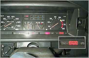
On the dashboard of vehicles equipped with this fuel injection system, a malfunction indicator lamp "CHECK ENGINE" is installed. It lights up when the ignition is turned on for 0.6 seconds. and signals about its serviceability and operability of system diagnostics. If there are temporary errors in the operation of the injection system, the control lamp "CHECK ENGINE" lights up for at least 10 seconds. When a malfunction is detected, the controller stores its code in RAM and lights up the "CHECK ENGINE" lamp, which indicates the need for diagnostics and troubleshooting. In the memory of the Electric Control Unit, a two-digit error code is stored (
12-99 ), which is indicated by this lamp when the self-diagnosis code output mode is initialized. Erasing error codes in the RAM of the controller occurs when the power is turned off. If you need to erase them, it is necessary to disconnect the positive terminal of the battery for 10-15 seconds with the ignition off. Accordingly, self-diagnosis should be carried out at least 10-20 minutes later. vehicle operation (better at different loads), after the last battery disconnection. --- ATTENTION --- If the battery is disconnected, the presets of critical additional devices (radio, alarm, etc.) may be lost. In this case, you can simply turn off the fuse of the Electrical Unit if no critical devices are connected to this circuit. Otherwise, you can remove the connector from the Electric Block itself. In addition, correction codes will be lost in the RAM, and until they are restored (up to 30 minutes of operation), it is worth refraining from dynamic driving and sudden accelerations. Diagnostic connector 
To initialize the mode of issuing diagnostic codes, it is necessary, when the ignition is off, to close the contacts " А
" And " В
"Diagnostic connector or contact"В"on the car body and turn on the ignition without starting the engine. The error code is displayed by flashing the "CHECK ENGINE" lamp in sequential form - first the high order, then (after a pause) the low one. For example: flash, pause, flash, flash will correspond to the code"12" - self-diagnosis performance. When this mode is initialized, the indicator will first give the code "12" and then three times each fault code. If the code is not displayed at the beginning of the test " 12
", means a malfunction in the Electric Control Unit itself. If there are no fault codes in the controller's memory, the "CHECK ENGINE" lamp will continue to display the code " 12
". In addition, in the code scan mode, the engine cooling fan relay and the air conditioning clutch relay (if installed) can be turned on, and the idle air control is set to stop additional air supply.
Controller diagnostic codes indicated by the "CHECK ENGINE" lamp * 13 - Low signal lambda probe
14 - Coolant temperature sensor signal low
15 - High coolant temperature sensor signal
16 - Overvoltage of the on-board network
17 - Undervoltage of the on-board network
* 23 - Intake air temperature sensor signal high
* 25 - Intake air temperature sensor signal low * 26 - Intake air temperature sensor signal high * 38 - Lambda probe signal error
* 41 - Phase sensor signal error
43 - Knock sensor signal error
* 44 - Lambda probe signal error when the fuel mixture is lean * 45 - Lambda probe signal error when the fuel mixture is enriched
51 - Read-only memory error
52 - Random access memory error
* 53 - EEPROM error * 54 - Octane corrector error
* 55 - Electronic control unit error * 61 - immobilizer error Codes marked with "*" may not be used, and the corresponding sensors may not be installed. It should be noted that the error codes read do not always clearly indicate a malfunction of any sensor or element of the injection system. When diagnosing, you should compare the controller data, the constructive response of the sensors and the specific behavior of the engine at idle and under load. Because the injection control system is constantly being improved, some fault codes may be missing in the table. After reading the error codes, turn off the ignition and after 10-15 seconds. remove the jumper on the diagnostic connector. Publication: cxem.net
See other articles Section Automobile. Electronic fuel injection
Machine for thinning flowers in gardens
02.05.2024 Advanced Infrared Microscope
02.05.2024 Air trap for insects
01.05.2024
▪ website section Data transfer ▪ magazines EKiS, Electronic components and systems (annual archives) ▪ book Household radio and sound-reproducing equipment. Directory. Alekseev Yu.P., 1994 ▪ article by Ghazali (Abu-Hamid Muhammad ibn-Muhammad al-Ghazali). Famous aphorisms ▪ article Digital tape recorder. Encyclopedia of radio electronics and electrical engineering ▪ article Electronic key K1233KT2. Encyclopedia of radio electronics and electrical engineering ▪ collection Archive of diagrams and service manuals for Fly Bird mobile phones
Home page | Library | Articles | Website map | Site Reviews
www.diagram.com.ua |

 Leave your comment on this article: