|
|


 Arabic
 Bengali
 Chinese
 English
 French
 German
 Hebrew
 Hindi
Hindi Italian
 Japanese
 Korean
 Malay
Malay Polish
 Portuguese
 Spanish
 Turkish
 Ukrainian
 Vietnamese
|
ENCYCLOPEDIA OF RADIO ELECTRONICS AND ELECTRICAL ENGINEERING Acoustic locator for the car. Encyclopedia of radio electronics and electrical engineering
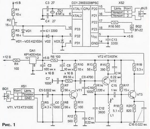
Encyclopedia of radio electronics and electrical engineering / Automobile. Electronic devices Driving in reverse, the driver of the car cannot see a certain area of the road space. This zone has a length of up to two meters, and people or animals, as well as objects that interfere with movement, can be in it. Achievements of modern technology make it possible to create special devices for viewing the specified space and informing the driver if any objects are encountered in the path of the car. This problem is most optimally solved with the help of pulsed acoustic location. Successful attempts to build such devices are known (see, for example, the book Siga X., Mizutani S. "Introduction to automotive electronics". - M.: Mir, 1989). However, due to complexity and high cost, these locators have not yet been widely used. The acoustic locator offered to readers is based on the Z8 microcontroller. It is simple, convenient for repetition by radio amateurs. With the appropriate refinement of the program and design, it can be used as an indispensable assistant for the blind, security devices, a portable echo sounder for an amateur fisherman, a non-contact liquid level indicator, etc. Schematic diagram of the locator is shown in fig. 1. Its basis is a microcontroller (MK) Z86E0208PSC (DD1).
The external timing circuit of the MK consists of a quartz resonator ZQ1 at a frequency of 8 MHz and capacitors C3. C4. The ultrasonic emitter BQ3 is connected directly to the pins of the P2 port of the MK. The amplitude of the excitation voltage at the input of the emitter is 10 V. The duration of the pulse train is 1 ms. The reflected signal received by the ultrasonic receiver BQ1 is fed to the input of a three-stage resonant amplifier made on transistors VT1-VT3. From its output, a signal with a constant component of 2.5 V is fed to the non-inverting input (P32) of the built-in comparator MK. An exemplary voltage of 2.7 V is supplied to the inverting input of the comparator (RZZ) from the divider R1R3. which ensures the selection of a useful reflected signal at the level of received interference. The reference voltage circuit is additionally protected from interference by a limiting diode VD1 and capacitor C1. Diodes VD2 and VD3 limit the instantaneous value of the reflected signal to levels of 0 and 5 V. An audible signal that warns the driver about the presence of an obstacle in the invisible zone is generated by the BQ2 piezoelectric emitter. connected through a resistor R16 directly to the pins of the P2 port of the MK. The locator is powered by a voltage of 12 ± 2.5 V from the purpose of the reverse signal lights of the car. Chip DA1 stabilizes the supply voltage at a level of 5 V, necessary for the normal operation of the MK. A filter is installed in the power supply circuit of the device, consisting of capacitors C2, C8, C13 and resistor R6. The principle of operation of the locator is based on the emission of a burst of pulses of ultrasonic frequency and the subsequent reception of a signal reflected by an obstacle. The time from the moment of emission to the moment of reception of the reflected signal is directly proportional to the distance to the object. Depending on the distance, the locator generates one of two warning sounds: if it is less than 1 m, frequent tone bursts are generated, if from 1 to 2 m - rare. At a distance of more than 2 m, there is no sound signal. The waiting time of the reflected signal is 60 ms, after which the next burst of pulses is emitted and the process is repeated. The operation of the device is explained in more detail by the graph [1], shown in Fig. 2 It includes four vertices - states: SEND (TRANSFER) - the formation of an ultrasonic burst of pulses; PRESS (SUPPRESSION) - suppression of aftersound emitter; WAIT (WAITING) - waiting for the reflected signal and COUNT (CALCULATION) - calculating the distance to the object.
The transitions between states, shown by the arcs of the graph, are caused by the following direct (indicated by one letter) and indirect (two letters in accordance with the transition) events: t (timer - timer) - operation of the MK timer, c (comparator - comparator) - operation of the MK comparator, ws (wait - send) - end of waiting for the reflected signal, cs (count - send) - end of calculation of the distance to the object and pw (press - wait) - end of the suppression time countdown. When the power is turned on, the device automatically resets and the SEND state is initialized. The main function of this state is to allow the formation of an ultrasonic burst of pulses with a duration of 1 ms. When triggered, the MK timer puts the device into the PRESS state, in which it does not respond to the received reflected signal. The duration of stay in this state is determined by the number of timer operations, which can be changed depending on the type of ultrasonic transducer used. At the end of the suppression time countdown, the next timer operation puts the device into the WAIT state. In the WAIT state, the locator waits for the arrival of a useful reflected signal, which triggers the MC comparator. memorization of the time from sending to receiving a useful signal and transition to the COUNT state. The process of counting time in the WAIT state is synchronized by the operation of the MK timer every millisecond. If after 60 ms in this state the MK comparator does not work, the device again switches to the SEND state. When the comparator fires, it goes into the COUNT state. In the COUNT state, the locator continues to count the 60 ms time interval. Then, based on the previously recorded time from the moment of sending to the moment of receiving the signal, the distance to the object is calculated. In accordance with the result of the calculation, the device controls the issuance of a sound signal with the required "signal-pause" interval. Upon completion of the calculations, it goes into the SEND state. Further, the cycle of operation is repeated. Any small-sized ceramic and oxide capacitors can be used in the locator. Coil L1 is wound on a single-section unified frame with a diameter of 8 and a winding section length of 7 mm. Trimmer - ferrite (100НН) with a diameter of 2,8 and a length of 12 mm. The coil contains 860 turns, wound turn to turn with PEL wire 0,15 (inductance 4.4 mH). Resistor R2 - SP5-2 or any other small-sized multi-turn trimmer. Piezoceramic sound emitter BQ2 - ЗП-22 or similar. Transistors VT1. VT3 - any of the KT3102 series. VT2 - any of the KT3107 series. The BQ3 ultrasonic transmitter and BQ1 receiver are identical. In the author's version, ultrasonic transducers from the Echo-2 security device produced by the industry are used; it is possible to use any suitable piezoceramic transducers, including self-made ones, with the same operating frequencies in the range of 36...38 kHz [2]. To connect them, imported DJK connectors are used (their DJK-2MR sockets are installed on the board, and the connecting cables are supplied with DJK-2F plugs). Codes "firmware" ROM MK are shown in the table. The amount of program code is 242 bytes.
Structurally, the locator consists of an electronic unit and an emitter and receiver of the same design. 3.
The board is placed in a plastic case from the radio designer "Communication Device" manufactured by JSC "Novgorod Machine-Building Plant". The appearance of the assembled locator is shown in fig. 4.
To reduce the acoustic effect of the emitter on the ultrasonic receiver, their acoustic paths are made in the form of horns. The horn, in addition, matches the relatively high impedance of the transducer with a rather low load impedance, i.e., air (3). The most effective exponential horn, the cross-sectional area of which varies according to the law S \u0d S0em, where S is the cross-sectional area of \u0b\u35bthe horn at a distance x from the transducer, S0,17 is the area of the horn inlet (at x \u1d XNUMX), i.e., the surface area of the transducer, m is the expansion coefficient of the horn, which depends on the operating frequency (for XNUMX kHz, m = XNUMX mm-XNUMX). At home, the easiest way is to make a horn, the cross section of which has the shape of a circle. Knowing that the area of the circle is πD2/4, calculate the diameter of the horn using the above formula at different distances x from the transducer (x can be limited to 15...20 mm). Then, according to the obtained values, a longitudinal profile of the horn is drawn on paper and a template is made from thick cardboard or tin. The horns themselves are made using this rigid foam template. The surfaces of finished horns are coated with paint to give them better acoustic properties. To protect against atmospheric action, the horns are placed in protective covers equipped with brackets for installation on the rear bumper of the car. It is convenient to use plastic wiring boxes as casings. Brackets are made from sheet steel. The gaps between the casing and the horn are filled with epoxy resin, and the entire structure is covered in several layers with weather-resistant synthetic enamel. Establishing the device begins with checking the installation for reliable connections and the absence of short circuits. Before installing the MK, it is advisable to check the operation of the voltage stabilizer and the ultrasonic signal amplifier. To do this, connect the power and measure the voltage at pin 5 of the MK panel. It should be within 5 ± 0.3 V. Then measure the constant voltage at terminal 9 of the MK panel (2.5 V ± 10%) and. by connecting a voltmeter to its output 10. set the voltage by 2 ... 0.2 V more than the first with a trimming resistor R0.3. Further, by connecting the input of the oscilloscope to terminal 9 of the MK panel and applying a sinusoidal signal with a frequency of 37 kHz and an amplitude of 3 mV to the input of the amplifier, a signal with an amplitude of 4.5 V is observed on the oscilloscope screen. By adjusting the inductance of the L1 coil, maximum gain is achieved at the specified frequency. After that, with the power off, a pre-programmed MC is installed in the panel and the device is connected to the emitter and receiver. If the device does not work when the power is turned on, connect the oscilloscope input (with an input resistance of at least 10 MΩ) to the XTAL2 terminal (pin 6) of the DD1 microcircuit and check whether the MK clock generator is excited. The absence of oscillations of a sinusoidal waveform with a frequency of 8 MHz indicates that the generator is not self-excited. In this case, you need to check the quartz resonator ZQ1 and capacitors C3 and C4. When installed on a car, the locator will be placed inside the passenger compartment, and the ultrasonic transducers - on the rear bumper at a distance of at least 0.6 m from one another. This distance provides the width of the working area of the locator equal to 2 m. By changing it. You can also adjust the width of this zone. Literature
Author: M.Gladstein, M.Sharov
Artificial leather for touch emulation
15.04.2024 Petgugu Global cat litter
15.04.2024 The attractiveness of caring men
14.04.2024
▪ Blu-ray Format Specifications Completed ▪ Made DNA analysis of the web ▪ Assessment of emotional stress in the cinema
▪ section of the site Note to the student. Article selection ▪ article by Jean de La Fontaine. Famous aphorisms ▪ article Xanthosoma arborifolia. Legends, cultivation, methods of application ▪ Article Means for washing hair. Simple recipes and tips ▪ Article Wonderful glass. Focus secret
Home page | Library | Articles | Website map | Site Reviews
www.diagram.com.ua |


 Leave your comment on this article: