|
|


 Arabic
 Bengali
 Chinese
 English
 French
 German
 Hebrew
 Hindi
Hindi Italian
 Japanese
 Korean
 Malay
Malay Polish
 Portuguese
 Spanish
 Turkish
 Ukrainian
 Vietnamese
|
ENCYCLOPEDIA OF RADIO ELECTRONICS AND ELECTRICAL ENGINEERING Radio microphone on the rfPIC12F675F chip. Encyclopedia of radio electronics and electrical engineering
Encyclopedia of radio electronics and electrical engineering / Audio equipment The device is a "pair" consisting of a radio microphone control panel and a radio microphone itself. Radio microphone control panel.
It is a transmitter operating in 100% AM mode at a frequency of 418 MHz. It is controlled by a controller that generates code packets. Operating time after any pressing of the button 7 sec. Kn1 - turns on the radio microphone for transmission for 1 minute. Kn2 - turns on the radio microphone for transmission for 10 minutes. Kn3 - turns on the radio microphone for transmission for 20 minutes. Useful power is about 15 mW. Current in transmit mode 20 mA.
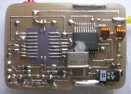
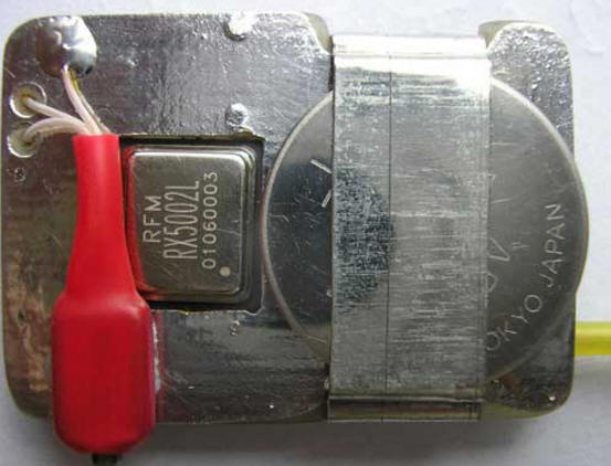
The actual radio microphone.
It deserves a closer look… It consists of a receiving part implemented on the RFM RX 5002 (418 MHz) microassembly, a decoder of the remote control commands and, at the same time, a transmitter on the rfPIC 12F 675 F, combined in one housing. The rfPIC 12F 675 F chip has several modifications, differing only in the possible transmitter frequency, set by an external quartz resonator. In this case, the output frequency will be 32 times the frequency of the external quartz. rfPIC 12F 675K (radiated frequency range from 290MHz to 350MHz) rfPIC 12F 675 F (radiated frequency range from 390 MHz to 450 MHz) rfPIC 12F 675 H radiated frequency range from 850 MHz to 930 MHz Despite the common housing, the rfPIC 12F 675 has no electrical connections with its own transmitter, and its processor part is completely identical to the regular PIC 12F 675. Therefore, when "flashing" (for example, with the IC Prog program), you need to select the name of the programmable microcircuit in the window - PIC 12F 675. Correspondence of rfPIC 12F 675 F pins to PIC 12F 675 pins (yellow) can be seen on the circuit diagram.
Device operation algorithm. Absolutely the same as in the "Remote Controlled Radio Microphone" described earlier. The microphone "sleeps" for 5 seconds (the current is 50 μA), then it "wakes up" and turns on the receiving part for 1 second (the current is 2,5 mA), waits for the turn-on signal, then "falls asleep" again. The cycle repeats continuously until the appropriate command is received. This device also provides for "direct" control (in real time), as in the previous design, if pin 3 of the rfPIC 12F 675 F controller is connected to a common bus. However, in this design, this mode is impractical to use due to the small difference between the receiving RX 5002 (418 MHz) and transmitting (416 MHz) frequencies. The real-time mode will probably be appropriate if you use a higher-frequency rfPIC 12F 675 H (850 MHz - 930 MHz), then with the help of a filter-plug it will be possible to "split" the receiver and transmitter operating into one antenna. In transmission mode, the current consumption is 15 mA. Customization. As can be seen from the circuit diagram, the device practically does not need to be configured. One has only to choose the capacitance at the input of the microphone amplifier (0,1 μF), which affects its frequency response and frequency deviation (100 k resistor) connected to the varicap. This version of the device was confidently listened to in the FM mode by the VR-120 scanner at a distance of more than 200 m. Firmware for the rfPIC 12F 675 F controller (the same applies to the PIC 12F 675). During the "filling" of the firmware file into the microcircuit (the IC Prog program is considered, an unforgivable mistake is often made - the loss of the internal calibration constant (erasing it by inattention), which does not damage the controller, however, the device may be inoperable. In order to correctly flash the microcircuit, you need ... 1) Read the freshly bought controller. The last cell of the program memory will contain a number (for example, 3488, as in the figure) 2) Write this number down on a piece of paper. 3) Open the file with the HEX extension (firmware). 4) Look in the open file in the last cell of the program memory. It will be empty (3FFF), because the HEX (firmware) file does not contain information about the constant for the internal peak generator, since it is individual for almost every crystal and is entered at the factory. 5) Rewrite what is on paper in the last cell of the program memory. That is, put the constant in place in the already open HEX - e. 6) Write HEX with a constant to the controller. Moreover, no settings of the configuration bits need to be changed (these are "birds" opposite the words WDT, PWRT, and so on). These settings are already "registered" in the firmware file and when it is opened, they themselves will become as needed.
List of radio elements
Author: Sergey (blaze), Kremenchuk, blaze2006@ukr.net
Machine for thinning flowers in gardens
02.05.2024 Advanced Infrared Microscope
02.05.2024 Air trap for insects
01.05.2024
▪ Solved the problem of quantum computers ▪ Nerve freezing may help fight obesity ▪ The TV is preparing to force the computer out of the apartment ▪ Smartphone as thick as a credit card
▪ site section Parameters, analogues, marking of radio components. Article selection ▪ article Theory and methods of education. Lecture notes ▪ article How does a snake charmer make a snake deaf to the sounds of a pipe dance? Detailed answer ▪ article Rock bow. Legends, cultivation, methods of application
Home page | Library | Articles | Website map | Site Reviews
www.diagram.com.ua | |||||||||||||||||||||||||||||||||||||||||||||||||||||||||||||||||||||||||||||||||||||||||||||||||||||||||||||||||||||||||||||||


 Leave your comment on this article: