|
|


 Arabic
 Bengali
 Chinese
 English
 French
 German
 Hebrew
 Hindi
Hindi Italian
 Japanese
 Korean
 Malay
Malay Polish
 Portuguese
 Spanish
 Turkish
 Ukrainian
 Vietnamese
|
ENCYCLOPEDIA OF RADIO ELECTRONICS AND ELECTRICAL ENGINEERING Antenna amplifiers SWA. Encyclopedia of radio electronics and electrical engineering
Encyclopedia of radio electronics and electrical engineering / Телевидение In the article published here, our regular author analyzes the circuitry of Polish-made antenna amplifiers and substantiates his conscious approach to their choice in terms of noise and gain. He also gives recommendations for the repair of such devices, which quite often fail from lightning discharges, and for the elimination of self-excitation. This will allow / hopefully many radio amateurs not only choose the necessary amplifier, but also improve its performance. Active antennas of the Polish company ANPREL and some others are widely used in Russia and the CIS countries. With a slight intrinsic gain, especially in the MB range, the parameters of such an antenna are largely determined by the antenna amplifier installed on it. It is this block that has a number of disadvantages: it is prone to self-excitation, has a rather high level of its own noise, is easily overloaded by powerful signals of the MB range, and is often damaged by lightning discharges. These problems are familiar to many owners of such antennas. The issues of operation of antenna amplifiers SWA and similar are very little covered in the literature. We can only note the publication [1], where it is indicated that the amplifier is overloaded with MB signals. The owners of antennas have to deal with the rest of the shortcomings in a known way: replacing amplifiers, choose the best one. However, this method requires a lot of time and effort, since the amplifier, as a rule, is difficult to access - it is located along with the antenna on a high mast. Based on the analysis of circuitry, my own experience and some materials from ANPREL, I propose a more conscious approach to the choice of amplifiers, as well as a repair method that allows you to restore a damaged unit, and in some cases improve its parameters. The market is filled with many interchangeable models of antenna amplifiers manufactured by ANPREL, TELTAD and others under various brand names and numbers. Despite this diversity, most of them are assembled according to a standard scheme and represent a two-stage aperiodic amplifier based on microwave bipolar transistors connected according to the OE scheme. In support of this, let's consider models from different companies: a simple SWA-36 amplifier from TELTAD, the schematic diagram of which is shown in Fig. 1, and the common amplifier SWA-49 (similar to SWA-9) from ANPREL - Fig. 2.
The SWA-36 amplifier contains two broadband amplification stages based on transistors VT1 and VT2. The signal from the antenna through a matching transformer (not shown in the diagram) and capacitor C1 enters the base of the transistor VT1, which is connected according to the OE circuit. The operating point of the transistor is set by the bias voltage determined by the resistor R1. The negative voltage feedback (NFB) acting in this case linearizes the characteristic of the first stage, stabilizes the position of the operating point, but slightly reduces its gain. There is no frequency correction in the first stage. The second stage is also made on a transistor according to the scheme with OE and with voltage feedback through resistors R2 and R3, but it also has current feedback through resistor R4 in the emitter circuit, which rigidly stabilizes the mode of transistor VT2. To avoid a large gain loss, resistor R4 is shunted in alternating current by capacitor C3, the capacitance of which is chosen relatively small (10 pF). As a result, at the lower frequencies of the range, the capacitance of the capacitor C3 turns out to be significant and the resulting AC feedback reduces the gain, thereby correcting the frequency response of the amplifier. The disadvantages of the SWA-36 amplifier include passive losses in the output circuit on the resistor R5, which is connected in such a way that both the constant supply voltage and the signal voltage drop across it. The SWA-49 amplifier is similarly built (Fig. 2), which also has two stages assembled according to the OE scheme. It differs from the SWA-36 in better power supply isolation through L1C6, R5C4 L-shaped filters and increased gain due to the presence of capacitor C5 in the OOS circuit (R3C5R6) of the second stage and the transition capacitor C7 at the output. Similar circuitry is inherent in most other SWA amplifiers (see, for example, the SWA-3 amplifier circuit shown in [1]). Minor differences are most often found in the second stage, which can be equipped with different frequency correction circuits, have different depth of feedback and, accordingly, the gain. For some models, for example SWA-7, the first and second stages are directly connected - the collector terminal of the transistor VT1 is connected directly to the base terminal of the transistor VT2. This makes it possible to cover both stages with a direct current feedback loop and thereby improve the thermal stability of the amplifier. In cascades on transistors connected according to the OE circuit, the influence of internal connections and capacitances of transistor junctions is the greatest. It manifests itself in the limitation of the bandwidth and the tendency of the amplifier to self-excitation, the probability of which is greater, the higher the gain. To evaluate it, the concept of the stability threshold is known - the limiting value of the gain, above which the amplifier turns into a generator. Many high-gain SWA antenna amplifiers operate near the stability threshold, which explains their frequent self-excitation. As measures to improve the stability of amplifiers, ANPREL uses different topologies of printed circuit boards (affecting the mounting capacitance), surface and bulk coils, chokes, etc. A more radical method: turning on transistors in a cascode circuit with OE-OB - for some reason is not used . With the same circuit for switching transistors with OE-OE, to solve the problem of stability, the company prefers to produce adjustable power supplies. By reducing its voltage, it is possible to eliminate the self-excitation of the amplifier while maintaining sufficient gain. The main parameters (noise figure Ksh and gain Ku) of the basic models of SWA amplifiers according to the ANPREL catalog are shown in Table. one. Let's consider the relationship of the main parameters with the circuitry of amplifiers and their influence on the reception quality. As is known, the gain at high frequencies in cascades with OE is critical to the parameters of the transistors used, especially to the cutoff frequency frp. The SWA amplifiers use bipolar microwave transistors of the npn structure, marked as T-67, less often - 415, which determine the maximum achievable gain coefficient Ku of a two-stage amplifier of about 40 dB. Of course, in such a wide operating frequency band, the gain does not remain constant - its changes reach 10 ... 15 dB due to uneven frequency response at higher frequencies of the range and correction at lower ones. At maximum values of the amplification coefficient Ku, it is difficult to ensure the stability of the amplifiers, therefore, in a number of models it is limited to values up to 10...30 dB, which in many cases is quite sufficient (see Table 1).
Contrary to popular belief, it should be noted that the gain cannot be considered the main parameter of the antenna amplifier. After all, the TVs themselves have a very large margin of their own gain, that is, they have a high sensitivity limited by gain. They have somewhat worse sensitivity, limited by synchronization. And finally, the lowest sensitivity is noise-limited [2]. Therefore, the factor that determines long-range reception should be the level of intrinsic noise of the electronic path, and not the gain. In other words, the reception limitation is primarily due to the influence of noise interference, and not due to a lack of signal amplification. The influence of noise is evaluated by the signal-to-noise ratio, the minimum value of which is taken equal to 20 [2]. With this ratio, the noise-limited sensitivity is determined, which is equal to the input signal voltage, which is 20 times greater than the intrinsic noise voltage. For televisions of the third to fifth generations, the sensitivity limited by noise is 50 ... 100 μV. However, with a signal-to-noise ratio of 20, very poor image quality is observed and only large details are intelligible. To obtain a good quality image, a useful signal should be applied to the TV input, approximately 5 times larger, i.e., a signal-to-noise ratio of about 100 should be provided [2]. The antenna amplifier must increase the signal-to-noise ratio, and for this it is necessary to amplify the signal, not the noise. But any electronic amplifier inevitably has its own noise, which amplifies along with the useful signal and degrades the signal-to-noise ratio. Therefore, the most important parameter of the antenna amplifier should be considered its noise figure Ksh. If it is not small enough, then increasing the gain is useless, since both signal and noise are amplified equally and their ratio does not improve. As a result, even with a sufficient signal level at the antenna input of the TV, the image will be affected by intense noise interference (the well-known "snow"). For a unified assessment of the noise of a multistage path, there is an indicator of the noise factor reduced to the input Ksh, which is equal to the noise level at the output divided by the total gain, i.e. Ksh=Ksh.out/Ku. Since the output noise level Ksh.out depends to the greatest extent on the noise level of the first transistor, amplified by all subsequent stages, the noise of the remaining stages can be neglected. Then Ksh.out = Ksh1Ku, where Ksh is the noise factor of the first transistor. Therefore, we get Ksh = Ksh1, i.e., the reduced noise figure of the amplifying path does not depend on the number of stages and the total gain, but is equal only to the noise figure of the first transistor. This leads to an important practical conclusion - the use of an antenna amplifier can give a positive result when the noise figure of the first transistor of the amplifier is less than the noise figure of the first stage of the TV. In the channel selectors of fifth-generation TVs, a KP327A field-effect transistor with a noise figure of 4,5 dB at a frequency of 800 MHz is used [1]. Therefore, in the first stage of the antenna amplifier, a transistor with Ksh4,5 <1 dB at the same frequency should work. Moreover, the smaller this value compared to the KshXNUMX coefficient of the TV, the more efficient the use of the amplifier and the higher the reception quality. The noise figure also depends on the quality of matching at the input of the amplifier and the operating mode of the first transistor. For SWA amplifiers, the type of transistor VT1, its mode of operation and the quality of matching determine the reduced coefficient Ksh = 1,7 ... 3,1 dB (see Table 1). From the above, it is clear that the choice of an antenna amplifier according to the principle - the greater the gain, the better - is incorrect. That is why many owners, changing amplifiers, cannot achieve a good result. The reason for such a paradoxical, at first glance, fact is that the noise figure is usually unknown (it is not in the trade information of firms), but in fact it differs only slightly for many models with different gains (see Table 1). ). Increasing the gain with the same noise figure does not give a gain in the signal-to-noise ratio and, therefore, an improvement in the quality of reception. A rare success is achieved only when a low-noise amplifier is accidentally encountered. Therefore, when choosing an antenna amplifier, you need to focus primarily on the minimum noise level. An amplifier with Ksh <2 dB can be considered quite good. From Table. 1, the best models can be considered SWA-7, SWA-9, having Ksh = 1,7 dB. Information about the noise figure of the new amplifiers can be found in the ANPREL catalogs or on the Internet. As for the gain, it, of course, also matters, but not for the maximum amplification of weak signals, but, first of all, to compensate for losses in the connecting cable, matching-branching devices, etc. Because of these losses If the gain is not sufficient, the signal level at the TV input may fall below the threshold, limited timing or even gain, making reception impossible. Therefore, for the correct choice of the gain factor, it is necessary to know the signal attenuation in the entire connecting path. And its approximate value is easy to calculate. The specific attenuation of the signal in the widespread cable brand RK-75-4-11 is 0,07 dB / m on the first to fifth, 0,13 dB / m on the sixth to twelfth and 0,25 ... 0,37 dB / m on 21 -60th television channels [2]. With a feeder length of 50 m, the attenuation on channels 21-60 will be 12,5...17,5 dB. If an industrial passive splitter is installed, it introduces additional losses at each of its outputs, the value of which, as a rule, is indicated on the case. By calculating the attenuation in the cable and adding to it the attenuation in the splitter (if any), the minimum gain of the antenna amplifier is obtained. A margin of 12 ... 14 dB is added to it to amplify weak signals, which is necessary due to the low efficiency of broadband small-sized receiving antennas. According to the obtained value of Ku, an antenna amplifier is selected. The obtained value of the gain should not be much exceeded, since this increases the likelihood of self-excitation and overload by powerful signals of closely spaced stations. Repair of antenna amplifiers is mainly reduced to the replacement of active elements damaged by lightning discharges. It should be noted that the presence of an input diode in some models does not guarantee complete lightning protection: with a powerful atmospheric discharge, both the protective diode and, as a rule, both transistors break through. Antenna amplifiers SWA are assembled using the technology of automatic surface assembly on microelements, which requires accuracy during repairs. Soldering should be done with a small-sized soldering iron with a sharply sharpened tip. In a non-working amplifier, carefully, trying not to damage the thin printed conductors, solder the microtransistors VT1, VT2 and the protective diode (if any). The main parameters of domestic transistors suitable for installation in SWA amplifiers are shown in Table. 2 [Z]. It follows from it that the use of transistors KT391A-2, KT3101A-2, KT3115A-2, KT3115B-2, KT3115V-2 in the first stage does not worsen the noise characteristics of most amplifier models, and the use of transistors 2T3124A-2, 2T3124B-2, 2T3124V- 2, KT3132A-2 reduces Ksh to 1,5 dB, which improves the parameters of the amplifier. This circumstance makes it possible to recommend replacing the first transistor of the amplifier with the last ones indicated even in serviceable but "noisy" amplifiers in order to improve the quality of their work. It should be noted that in Table. 2 limits are given, typical parameters are usually better [XNUMX].
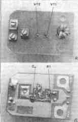
Low-noise microwave transistors of the 2T3124, KT3132 series are relatively expensive and low-current, so it is better to install them only in the first stage, and in the second one use cheaper and more powerful transistors KT391A-2, KT3101A-2 (see Table 2) and even the KT371, KT372 series , KT382, KT399 and others with a cutoff frequency of about 2 GHz [XNUMX]. However, in the latter case, the gain at the upper frequencies of the range will be slightly less. The body dimensions of imported microtransistors are 1,2x2,8 mm with lead lengths of 1...1.5 mm. Accordingly, the distances on the board between the printed pads for the outputs of transistors are small. The installation of domestic transistors with a case diameter of 2 mm from the side of surface mounting, although possible, is difficult: they can be damaged during soldering. It is better to install new transistors on the opposite side of the board, having previously drilled holes for the leads with a drill with a diameter of 0,5 ... 0,8 mm. It is better to drill not in the printed conductor itself, but so that the hole touches the edge of the pad. If there is a layer of foil on the side opposite to surface mounting, then the holes in it should be countersunk with a drill with a diameter of 2 ... 2,5 mm (except for the hole for outputting the emitter of the transistor VT1). Then new transistors are installed so that the crystal holder or device case touches the board. If the leads protrude significantly on the other side, they should be bitten off after soldering. Microwave transistors are sensitive to static electricity, so appropriate safety precautions must be taken when soldering. Soldering time - no more than 3 s [З]. The protective diode can be omitted. The best protection against atmospheric electricity is a good grounding of the antenna. In SWA amplifiers, both transistors operate with a collector current of 10 ... 12 mA. After replacement, such a current is acceptable for the second transistor (for example, KT3101A-2), but exceeds the permanently permissible for the first if transistors of the KT3115, KT3124 and KT3132A-2 series are installed (see Table 2). The collector current depends on the parameter h21e, in which the transistors have a significant spread. Therefore, after mounting a specific instance, it is necessary to set the operating point of the transistor VT1. To do this, solder the microresistor R1 and instead temporarily connect a tuning resistor (SPZ-23, SPZ-27, etc.) with a resistance of 68 ... 100 kOhm. Before turning on the power, the resistor slider must be in the position of maximum resistance so as not to damage the transistor. The amplifier is supplied with voltage 12 8 from the power supply and the voltage drop across the resistor R2 is measured (see Fig. 1 and 2). By dividing the measured voltage by the resistance of the resistor R2, the collector current is found out. By adjusting the resistance of the tuning resistor downwards, a collector current of about 5 mA is achieved, which corresponds to a minimum of noise according to the characteristic of transistors [0,125]. This completes the tuning and instead of a tuning resistor, a constant of the same resistance (MLT-XNUMX or imported) is soldered in, having previously shortened its conclusions to a minimum. After that, the printed circuit board and packageless transistors are covered with a layer of radio engineering varnish or compound. The appearance of the restored SWA-36 amplifier is shown in fig. 3. It uses transistors (Fig. 3a) 2T3124B-2 (VT1) and KT3101A-2 (VT2). In connection with the simplest design of the amplifier, measures were taken to eliminate self-excitation: a ferrite microring is put on the output of the collector of the transistor VT1 (it is used in the SK-M channel selectors of ZUSCT and 4USCT TVs). The collector current of the transistor VT1 is set by the resistor R1 (Fig. 3,6) with a nominal value of 51 kOhm (it was 33 kOhm).
In the second stage, transistors of the KT372, KT399 series were tested, with which stability and a sufficient gain were maintained. At the same time, the possibility of installing an additional capacitor Cd with a capacity of 150 pF (Fig. 3,6), shunting resistor R5 (see Fig. 1), was checked to increase the gain. When installing a capacitor, self-excitation of the amplifier is eliminated by lowering the supply voltage. In the main version (with transistors 2T3124B-2 and KT3101A-2), the amplifier provided better reception quality than before the repair, which was visually estimated to be approximately the same as the reception with the new SWA-9 amplifier. Literature
Author: A.Pakhomov, Zernograd, Rostov Region; Publication: N. Bolshakov, rf.atnn.ru
Energy from space for Starship
08.05.2024 New method for creating powerful batteries
08.05.2024 Alcohol content of warm beer
07.05.2024
▪ Impact of electric cars on the environment ▪ Toyota Mirai hydrogen sedan billboards purify the air ▪ The sustainable way to recycle lithium-ion batteries
▪ site section Indicators, sensors, detectors. Article selection ▪ article Dance of St. Vitus (Witt's Dance). Popular expression ▪ article Who steals valuables from Diego Maradona in Italy from time to time? Detailed answer ▪ article Accountant for accounting of borrowed funds. Job description ▪ article Crayons (for wood, leather, fabric, etc.). Simple recipes and tips ▪ article The coin passes through the rubber. Focus Secret
Home page | Library | Articles | Website map | Site Reviews
www.diagram.com.ua |

 Leave your comment on this article: