|
|


 Arabic
 Bengali
 Chinese
 English
 French
 German
 Hebrew
 Hindi
Hindi Italian
 Japanese
 Korean
 Malay
Malay Polish
 Portuguese
 Spanish
 Turkish
 Ukrainian
 Vietnamese
|
ENCYCLOPEDIA OF RADIO ELECTRONICS AND ELECTRICAL ENGINEERING Multiband directional antennas. Encyclopedia of radio electronics and electrical engineering
Encyclopedia of radio electronics and electrical engineering / HF antennas Many radio amateurs dream of a multi-band directional antenna. There are a number of technical solutions that allow you to create such a design, but not all of them are easily reproducible in amateur conditions. The author of this article offers readers his own version of the implementation of a compact five-band directional antenna. A directional rotating KB antenna for 5 bands (10 - 20 meters) and even for 7 bands (10 -40 m) is an actual amateur radio design. Most of the world's leading manufacturers of amateur radio antennas have several five-band antennas in their product range, which differ in performance and price. Each of the firms, as a rule, uses its own well-established and standard methods for implementing multi-range. For example, FORCE 12 uses an intermittent arrangement of elements of different ranges (models XR5, 5VA), MOSLEY - a large number of resonant traps (PRO-67, PRO-96), HY-GAIN - a log-periodic active element in combination with "trap" directors (TH- 11), TITANEX - a variety of log-periodic wire antennas. The novelty was proposed by the SteppIR company - the elements of its antenna change their dimensions with the help of an electromechanical drive according to the commands of the microprocessor device located below. The proposed article briefly discusses the main advantages and disadvantages of standard methods for creating MDA (Multi-Band Antennas) and describes its own version, which allows, in the dimensions of a three-element VK (Wave Channel) range of 20 meters with a boom length of less than 6 m, to obtain a five-band (10, 12, 15, 17 and 20 meters) antenna. The total number of elements is 16, and the mutual influence of the elements is minimized without the use of ladders. The characteristics of the antenna on each of the ranges practically correspond to a three-element VK (!). The peculiarity of this variant is that parts of the 20-meter range director cut off with the help of two vacuum relays are used as 10 and 15-meter range directors. The antenna uses a five-band active element with a simple matching circuit, which made it possible to feed it with one cable without switching. Characteristics of applied MDA For the analysis of MDA, both the data presented in the literature and calculations using the computer program for antenna modeling MMANA [1] were used. As a rule, when developing such antennas, they strive to obtain characteristics corresponding to a two- or three-element VC on certain bands, so you should start by determining these characteristics. We will use the notation adopted in MMANA:
Let us calculate the characteristics of a three-element VC. This can be done for any frequency. Let's take f \u28,3d 10,6 MHz (X \u600d \u28,0d 28,6 m), the operating frequency band is 10 kHz (0,3 ... 0,3 MHz), the radius of the conductor r \u0,4d XNUMX mm. When optimizing the antenna, the weighting coefficients for the SWR, Gh and F/B parameters are taken equal to XNUMX, respectively; XNUMX and XNUMX. We will calculate for three options:
Calculation conditions - the antenna is in free space, F/B is determined for zero elevation. The calculated data are summarized in table. 1. Three numbers separated by a slash correspond to the parameter values at the beginning (28 MHz), middle and end of the operating frequency band. When calculating BW, we proceed from the fact that a matching device SU is used at the antenna input, which provides SWR = 1 at the average frequency. The data given in the fourth row of this table will be discussed further in the section "Mutual influence of passive VC elements on different bands".
When the calculated frequency changes, the width of the operating frequency band changes proportionally. For example, at f = 14,15 MHz, the parameters G and F / B will be the same as in Table. 1, but in the 0,3 MHz band. Also, the BW value will be 2 times less (provided that the radius of the elements will be increased proportionally, i.e. 2 times). Shortened elements Most often, shortening is achieved by including an inductor in each element arm [2]. In this case, a number of characteristics of the elements deteriorate, primarily their broadband. A tangible contribution to the narrowing of the working band can be made by the parasitic capacitance between the turns of the coil C0. For example, the coil has L = 10 µH and C0 = 2 pF. At a frequency f = 28 MHz XL = coL = j1760 ohm and Xc = 1/ωС = -j2664 ohm. The resistance of the parallel circuit of L and C0 will be Xn = j[1760x(-2664)/(1760-2664)] = = j5187 ohm. It turns out that, taking into account the influence of C0, the real value of the reactive resistance of the "coil" has increased by 5187/1760 = 2,95 times (the loss resistance has correspondingly increased), and the equivalent inductance of the circuit will be XLeq = 10x2,95 = 29,5 μH. The main problem that arises due to the presence of C0 is that, along with an increase in the inductive resistance of the circuit, the rate of its change also increases when moving from one operating frequency to another. So, in the case of a coil with zero C0, when the operating frequency changes by, say, one percent, the resistance of the XL coil will also change by one percent, and for our circuit the change will already be much larger - about 5%. The obvious conclusion is that the capacitance C0 should be as small as possible. This is achieved by single-row winding of the wire (preferably with a small step) on a frame of small diameter. Here is the experimental data. A coil made of MGTF wire with an insulation diameter of 1,55 mm, a frame diameter of 23 mm, the number of turns n = 41 (winding turn to turn) had a measured inductance L = 13 μH and a quality factor Q = 260. Using GIR, the resonant frequency of the circuit was determined LCD (it turned out to be equal to fn = 42 MHz) and by calculation (MMANA) the value C0 = 1,1 pF was obtained. From the same wire, another coil was made on a frame with a diameter of 50 mm. Her data is n = 20, L = 19 μH, Q = 340, f0 = 25MHz and C0 = 2,13pF. Dipole with ladders Consider a dipole designed to operate on the 10 and 15 meters bands, the dual-band operation of which is ensured by the use of resonant LC-traps tuned to the upper frequency f1 = 28,5 MHz. At frequencies of the 15-meter range, the resistance of the ladder Xt is inductive in nature and its value is determined by the values of Lt and St (St also includes C0). Obviously, the presence of the capacitor St will affect the dipole broadband BW in the same way as the turn-to-turn capacitance C0. Let us calculate the bandwidth BW1,5 first for single full-size dipoles with resonant frequencies f1 = 28,5 (dipole 1) and f2 = 21,2 MHz (dipole 2), and then for a dual-band trap antenna. We will make calculations for three options for traps (trap 1, trap 2 and trap 3) with capacitance values of trap capacitors - 15, 25 and 35 pF (inductance 1_t, respectively, 2,08, 1,25 and 0,89 μH) with a quality factor of the coils Q = 150 and conductor radius r = 15 mm. The results of the calculation are given in table. 2. The numbers in parentheses show what percentage of the full-width dipole bandwidth the trap antenna has on that band.
The calculation shows that such an antenna is significantly, 1,5 ... 3 times, inferior to a full-sized one in terms of broadband. Since this is due, first of all, to a faster increase in the input (intrinsic) reactivity, when using trap elements as passive, the F / B indicator will also change much faster within the range. It follows from the calculated data that the dependence of the broadband trap antenna on the upper (10 meters) and lower (15 meters) ranges on the value of St has the opposite character and the choice of the value of St is a compromise task. In the upper range, the greater the value of LT (less than St), the higher the resonant resistance of the trap circuit and the less its effect on the antenna broadband in this range. But at the lower one, with an increase in Lt, the total length of the antenna decreases and, accordingly, its broadband. We note an interesting feature - shortened passive elements make it possible to obtain a better F / B index than full-size ones, but in a narrow frequency band. As for the losses in the trap antenna, the calculation gives the following values: in a three-band single dipole 7,4 m long with two pairs of traps with a quality factor of the coils Q = 150, the loss on the range of 10 meters is 0,14 dB, 15 meters is 0,78 dB and 20 meters - 0,59 dB. In VC with trap elements, the total loss can exceed 1 dB. Mutual influence of passive elements of VC of different ranges It is known that when antennas of different bands are placed on the same boom, the elements of lower-frequency antennas can greatly affect the parameters of the antennas of the upper bands [3]. To assess this effect, we will calculate the parameters of a three-element VK-10 for a range of 10 meters (fo = 28,5 MHz, see Table 1, line 1), located in the "environment" of longer passive elements. For definiteness, we assume that these are directors and reflectors of the VK ranges of 15 and 20 meters. The lengths of the elements D15, R15 and D20, R20, as well as their radii and distances from the center, are set based on the similar dimensions D10 and R10, taking into account the similarity coefficients (frequency ratios) K15 - 28,3 / 21,2 = 1,33 and K20 = 28,3 ,14,15/ /2 = 1 (Fig. 10). The calculation is carried out in stages. We calculate the SWR and BW band using an external matching device. At each stage, the VK-3 parameter optimization mechanism is used. The calculation results are summarized in table. XNUMX.
The performed calculation (lines 1 and 2) shows that the conductors located behind the P10 reflector practically do not affect the VK-10 parameters. This is because the field behind the reflector is very weak and no noticeable current can occur in the "rear" conductors. The location of the reflectors, as in Fig. 1 is widely used in multi-band antennas, especially when using a multi-band active element, for example, with traps or LOM coils [4]. In the case of the location of longer elements "ahead" of the VK-10 (in the zone of a strong field), the currents in these elements reach a significant value. Their influence sharply worsens the quality indicators of VK-10 (lines 3, 4, 5), so such options should be avoided. As an exception, a variant is possible when the "long" conductor is located in the near zone of the active element (at a distance of 0,05L, line 6) [3].
Actually, the question of the application (location) of director elements is one of the main ones in the development of a multi-band antenna. As an example, consider a variant of a combined antenna consisting of a three-element VK-20 with optimal inter-element distances and a four-element VK-10 (Fig. 2). The calculation of VK-20 shows that its performance is almost the same as the data in Table. 1 (line 1). Then, the calculation (optimization) of the VK-10 indicators was carried out. For convenience of comparison with the performance of an uncombined three-element antenna, the calculated data are placed in Table. 1, line 4. It can be seen that the addition of the second director D10 made it possible to largely overcome the negative impact of D20 and the four-element VK-10 in terms of G and F / B came close to the three-element one (!), but significantly inferior in terms of broadband. Another example is a combined 14-element three-band antenna type C-31XR (FORCE-12) with a boom length of 9,3 m. On the 10-meter band, the antenna provides a gain of 7,3 dBd using seven elements of this band [5]. The calculation shows that such amplification can be provided by only four elements, therefore, the action of the remaining three is aimed at compensating for the "negative" influence of the lower range directors. When building a five-band (10-20 meters) antenna, the use of the compensation principle is unlikely due to excessive complexity. Multi-range active elements In addition to the long-used trap and log-periodic emitters, other relatively new types are also used. One of the popular three-band designs is shown in Figure 3.
It consists of a split dipole for a range of 20 meters and located at a distance of 0,1 ... 0,5 m of two conductors with lengths close to 0,5λ for ranges of 15 and 10 meters. Due to the strong electromagnetic coupling between them, the system has three resonant frequencies. By selecting the length of the conductors and their distance to the dipole, you can get the desired value of the input impedance on the ranges of 10 and 15 meters in both simple and multi-element antennas. This design is called open sleeve or CR (coupled resonator) [6]. The disadvantage of this option is the relative narrow band. In particular, in order to cover the entire range of 10 meters, it is necessary to use two resonator conductors of different lengths. One of them provides operation in the lower section of 28,0 ... 29,0 MHz, and the second - 29,0 ... 29,7 MHz. Good results can be obtained by connecting several closely spaced dipoles with different resonant frequencies in parallel. With distances between individual dipoles of 0,3 ... 0,5 m, such an active element can provide normal performance in the ranges of 12, 15, 17 and 20 meters, and in combination with other methods - in the ranges of 10, 30 and 40 meters [ 4]. Different types of five-band antennas (specific samples) Logoperiodics. A sample with very high characteristics for this class of antennas is given in [7]. Range - from 14 to 30 MHz, number of elements - 13, boom length - 10,97 m, gain within the range from 4,85 to 5,65 dBd, F/B - 20...26 dB. Another design is described in THE ARRL ANTENNA HANDBOOK and has more modest parameters - boom length 7,8 m, 12 elements, gain 4,4.. .4,6 dBd and F/B - 14...21 dB. In both designs, the elements were made of tubes with a diameter of about 25 mm. Keep in mind that the antenna gain decreases as the diameter of the elements decreases, so a wire version will require more elements than a tube antenna with the same gain. The presence of a collecting line and the need to isolate the elements from the boom significantly complicates and makes the design heavier. Undoubted "plus" LPA - only one feeder line. In a log-periodic with a large number of elements within each of the relatively narrow amateur radio bands, as a rule, only three elements are actively working. Due to the characteristics of the LPA, these elements are used less efficiently than in the composition of a "narrow-band" VC. Therefore, if five three-element VCs are placed sequentially, one after the other, on the 10, 12,15, 17 and 20 meters bands on a long boom, you can get a greater gain than in a log-periodic with the same number of elements. The design flaws of such a construction are obvious - a large number of feeder lines (five) and a very long boom length. One way to solve the problem can be seen in Fig. 4.
This is a 5VA model from FORCE 12. The declared characteristics of this antenna are: gain - within 5,4 ... 5,9 dBd, F / B - 14 ... 23 dB, paper length - 9,9 m, 15 elements, 3 feeder lines. The price of the antenna is about 1300 USD. Antenna VMA 5 The VMA-5 five-band directional antenna was developed by the author of this article. Here is her data:
All the data obtained as a result of the calculation - the antenna circuit, the shape and geometric dimensions of the conductors-elements, reactive loads, as well as electrical indicators by ranges are in the VMA-5 file. The general view of the antenna is shown in the photo (Fig. 5)
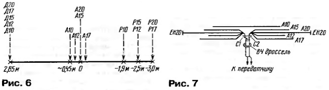
It consists of two assemblies - director and active, and a number of reflectors located on the boom according to Fig. 6. The coordinates of the elements on the boom are set in relation to the active element of the range of 20 meters (A20), the position of which is taken as the zero mark. Wire reflectors P12 and P17 are mounted respectively above the tube reflectors P15 and P20 in such a way that their middle is at a height of 0,5 m, and the edges are 0,15 m above the tubes.
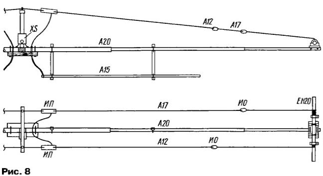
The electrical circuit of the active part of the antenna is shown in fig. 7. It consists of four separate active elements A12, A15, A17, A20, connected in parallel to each other and through "shortening" capacitors C1 and C2 with a power cable, and a separate field-coupled dipole A10 ("open sleeve" system) . Coordination on the range of 10 meters is achieved by selecting the length of the A10 and its distance from the main group. The lengths of the dipoles A12 - A20 are chosen more than the resonant ones in such a way that the input resistance (active part) rises to Ra ≈ 50 Ohm. By selecting the length of the dipoles and the capacitance of the compensating capacitors C1 and C2, as well as the position of the passive elements on the boom and their settings (length), it was possible to obtain SWR = 1,05 ... 1,25 at medium frequencies of all ranges. The design of the active assembly is shown in fig. 8 in two projections (the assembly is symmetrical, only one half is shown). IP insulators - plastic insulators of the A1001 type ("Antennopolis", Zaporozhye), IO - nut insulators.
The assembly is based on the A20 element, made of duralumin pipes with diameters (external/internal) 35/30 + 30/26 + 30/27 with a total length of 10 m. Small capacitive loads EH20 are fixed at the ends of the A20. The use of EH20 allowed:
A double-folded polypropylene cable with a diameter of about 3 mm was used as braces. The guy pre-tensioned with a force of 5...10 kg is screwed onto the EH20 tube (10...15 turns), then the end of the guy is fixed with a clamp. The adopted curved shape of the A12 and A17 made it possible to increase the distance between the A20 and the wire vibrators and thereby reduce mutual influences. In addition, they successfully perform the role of stretch marks that protect the heavy A20 from severe deflection, especially in the case of ice. Element A15 is fixed below A20 at a distance of 0,38 m using four dielectric spacers. At the selected distance, the bandwidth of the A15 decreases slightly - by about 10%. As the initial sections of A15, segments of a flexible cable PK75-4 were used (the braid and the core are soldered together). You can use any copper stranded wire with a diameter of 5 ... 8 mm in weatherproof insulation, but it will be both more expensive and heavier. Balancing is carried out using a protective choke of 15 turns of the RG-58 coaxial cable, wound on a ferrite magnetic circuit with an outer diameter of 65 mm and a permeability of 300. For a power of more than 200 W, a more powerful cable should be used. The inductor and capacitors C1, C2 of the K15U-2 type of 200 pF are placed in a textolite box with external dimensions of 130x140x45 mm, a coaxial angle connector XS of the SR50-153F type is attached to the bottom of the box. The box is attached to a vertical bracket, made, like the upper horizontal crossbar, of steel thin-walled square-shaped steel with dimensions of 20x20 mm. The mechanical connection of the A20 halves is carried out using a sleeve-insert, machined from a solid fiberglass rod, the gap between the halves is 50 mm. A20 is attached to a fiberglass board with dimensions of 225x100x19 mm using two U-shaped studs made of stainless wire with a diameter of 6 mm. The active assembly A12-A20 is one easily removable assembly. The A10 element is attached to the boom separately using a U-bracket and wing nuts. The electrical circuit of the director assembly is shown in fig. 9. It includes director elements for all five ranges. The structural basis of the assembly is the middle element, consisting of three isolated sections a-b, c-d, e-f, which can be interconnected using relay contacts K1.1 and K2.1.
If both relays are turned on and the contacts are closed, a 20 meter band director (D20) is obtained, about 9,65 m long. When only one of the relays is turned on, a 15 meter band director element (D15) is obtained. This will be element a-b-c-d or c-d-e-f, depending on which relay is on and which is off. Since D15 is located asymmetrically with respect to the axis of the antenna (boom), then the radiation pattern (DN) will also be somewhat asymmetrical. The calculation shows that the front lobe of the RP deviates slightly from the antenna axis - by about 5 degrees, but this is not accompanied by a drop in gain (deformation of the rear lobe will be shown below). When both relays are off, end sections a-b and e-f act as two 10m band directors. The lengths of these sections are insufficient for normal operation, so two capacitive loads EH10 are installed at the inner ends of the sections (b and e). Such a double director affects the antenna parameters on this range in almost the same way as a regular single director located right on the boom. It can be noted that in D15 and D20 (with closed relay contacts) the influence of EH10 is insignificant. With this method of "organization" of the directors of the three main ranges, their mutual negative influences are completely excluded, as well as their influences (with open contacts of the relay K1, K2) and on the ranges of 12 and 17 meters. In addition, the consumption of duralumin pipes will decrease by about 11 m, as well as the windage and weight of the antenna. The director assembly is located at a distance of 2,85 m from A20. This is a compromise value. Longer distances will rapidly decrease F/B on 10 meters, while shorter distances will degrade most performance on 20 meters. The director uses high-frequency vacuum relays (switches) V1 V-1V with allowable values of 1=10 A and U=3 kV. The calculation shows that such a current and voltage in the director correspond to an antenna input power of at least 5 kW. The temperature range of the relay is from -60° to +100°, the guaranteed number of switchings is 100000. The measured value of the "through" capacitance of an open relay is about 0,9 pF, taking into account the parasitic capacitance of the installation, the value of 1,5 pF is included in the calculation model (table of loads, pulse w35c, w36c). The closed state of the relay corresponds to the same loads, but already with a value of 100000 pF (short circuit equivalent, see "comment" to the VMA-5 file). The calculation shows that it is permissible to use a relay with a "through" capacitance of up to 5 pF with the adjustment of the dimensions of the components D20 and EH10. In particular, you can try the common REN-33 hermetic relays with parallel-series connection of all four contact groups. The directors of the ranges of 12 meters (D12) and 17 meters (D17) are made of wire. To eliminate the negative impact of these elements on the parameters of higher frequency ranges, the following measures have been taken. 1. The directors of all five ranges are located in the same vertical plane. As calculations show, with such an arrangement, their mutual influences decrease. 2. The possible strong influence of D12 on the range of 10 meters (along its length, D12 would be a full-fledged reflector on the range of 10 meters) is eliminated with the help of a parallel circuit - anti-trap L12C12 with a tuning frequency of 28,3 MHz, installed in the middle part of D12. Why antitrap? The purpose of the ladder is to separate from the antenna element a part whose dimensions are close to resonant. The purpose of the antitrap is the opposite - to cut the element into segments, the dimensions of which are much smaller than the resonant ones. In order not to affect the broadband range of 12 meters, unusually low reactances were adopted - C12=150 pF and 1.12=0,21 μH, which is 8...10 times less than the standard ones for a trap. Despite this, the resonant resistance of the circuit is sufficient to perform its main function. A loop of connection Lc is provided, through which, using a bridge-type SWR meter, you can determine the resonant frequency of the circuit. 3. The inductance L17 = 17 μH is included in the middle part of D4. This leads to someone that when operating at frequencies of 21 MHz and higher, the current induced in D17 decreases significantly - L17, as it were, cuts D17 into two halves. Due to this, the deterioration of the F / B index in the upper ranges under the influence of D17 does not exceed 1 dB. In order to simplify the design, L17 is made of two identical closely spaced coils (L17' and L17 ") with an inductance of 2 μH each. The introduction of L17, of course, worsens the broadband parameters of the antenna on the 17-meter band, but this is already noticeable outside the working frequency range (see Table 4).
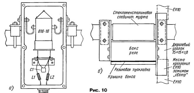
The design of the middle part with the assembly directory is shown in Fig. 10. The pipes used are the central part with a diameter of 30/26 mm, insulating inserts from fiberglass rods, end sections from pipes with diameters of 30/27 and 22/20 mm, capacitive loads - 16/13,8 mm.
The middle part D20 is attached to the boom through a glass-textolite plate (Fig. 10, a) with dimensions of 270x95x12 mm. Each of the L17 coils is wound on a plastic antenna insulator type A1001 with the same wire as in D17 (Fig. 10,6). On fig. 11 shows a box (a box with dimensions of 70x120x35 mm, milled from textolite) with a V1V-1V relay and a method for attaching it to D20 (easy-to-remove mount). Power is supplied to the relay through the RS4GV connector. The relay power wires are divided into sections about 2 m long using DPM-1,2 type chokes, 15 μH each. In their middle part, the wires are tied to a transverse bracket. Capacitor C1 - K31-11-3 with a capacity of 2000 pF.
Due to the asymmetric location of the D15, currents can be induced on the boom, which will lead to additional asymmetry of the pattern on the 15-meter range. To avoid this trouble, the extreme part of the boom (on the side of the directors) 2 m long is separated from the rest of the boom by a textolite insert. Antenna testing and calculation of electrical parameters were carried out in relation to its position in free space. With an antenna height above the ground of more than 20 m, its parameters will not change very much. There are two options for calculations: to achieve the maximum possible G and F / B indicators in some part of the range and to achieve the greatest uniformity of indicators within the entire range. In the second case, at the middle frequency of the range, the gain will be less by 0,2 ... 0,4 dB. An option was chosen in which the parameters are optimized for sections of the ranges 14,0 ... 14,3, 21.0 ... 21,4 and 28,0.-28,6 MHz. If the optimization also covered the upper, little-used sections of the ranges, this would inevitably worsen the performance "below", in the telegraph sections. For the bands of 12 and 17 meters, the calculation is made for the maximum F / B at medium frequencies. The calculation results are summarized in Table. 4. A note about the values of the F/B parameter marked with an asterisk * at frequencies of 21,0 and 21,4 MHz. On fig. 12 and 13 show two DNs for the same frequency of 21,0 MHz, which are obtained depending on which of the relays K1 or K2 is turned on. These MDs practically differ only in the shape of the rear part (mirror symmetry). Since the relays are operatively controlled from the radio remote control, interference from any direction in the rear half-plane, as can be seen from the figures, can be suppressed by 21 ... 24 dB. For comparison, in Fig. 14 shows the DN at the center frequency of 21,2 MHz.
The 5VA antennas (FORCE-12) and the 13-element LPA mentioned in the first part of the article are close to VMA-5 in electrical parameters. The declared parameters of 5VA have already been mentioned above: gain - within 5,4 ... 5,9 dBd, F / B - from 14 to 23 dB, boom length - 9,9 m, 15 elements, 3 feeder lines. At the same time, the consumption of duralumin tubes is: VMA-5 - 63 m (taking into account the boom and capacitive loads), 5VA - about 110 m, LPA - about 100 m. It is also obvious that the last two antennas have significantly greater wind resistance and weight.
The design of the VMA-5 is experimental in nature: all tubular elements have adjustable end sections, the length of the wire elements is adjustable in the end insulators, and the elements can be moved along the boom. This makes it possible in the experiment, if necessary, to refine the calculated data.
In particular, the calculation did not take into account the influence of the "ground", primarily due to the fact that in the author's QTH in different directions from the antenna, the parameters of the ground differ dramatically. The antenna made according to the calculated data was initially installed at a height of 1,8 m above the ridge of the slate roof, and with a slight adjustment of the lengths of the active elements (lengths of EH20 in A20), the resonant frequencies were set to "their places" using an SWR meter. This was followed by climbing to a working height - 6,5 m above the ridge of a four-story house and 25 m above the ground and checking the parameters. The main F/B check on three frequencies of each band was carried out using the signals of the local radio station UT1MQ in the receive mode. The receiver turned on manual gain control, the signal level at the low-frequency output was monitored using a V7-37 voltmeter. The measured F/B values were within 18...30 dB. An interesting experiment was carried out with Arthur (4X4DZ). Within 20 minutes, both sides "rotated" their antennas to each other (Arthur's - TN-11) on all five bands, the result on both sides is approximately the same - F / B at an average level of 20 dB (4 ... XNUMX points). The SWR value and the BW band are close to the calculated ones, serious measurements of the antenna gain have not yet been carried out. The VMA-5 design has some differences from the design model:
It should also be noted that reactive loads in the program are specified as point loads, while real L and C have their own lengths, and this may affect the accuracy of the calculation. On the basis of VMA-5, a model of a seven-band antenna was developed, which also includes two elements each for 30 and 40 meters. Perhaps, over time, this model will be implemented in hardware. Part of this model - an active element for a range of 40 meters (A40) has already been applied (as an addition) to the existing antenna (see Fig. 5 - photo). The A40 is based on the A20 by adding a coil with an inductance of 20 μH to each of its ends and a 1,41 m long end section (LOM technology). The lengths of the capacitive loads had to be slightly increased. In conclusion, it can be noted that electromagnetic relays are beginning to appear both in branded antennas (MAGNUM 280 FORCE-12, TITAN EX, etc.) and in amateur designs [8]. The author is grateful to Boris Kataev (UR1MQ) for his great help during the installation of the VMA-5 and Alexander Pogudin (UT1MQ) for participation in the measurements. Literature
Author: Ernest Gutkin (UT1MA), Lugansk, Ukraine
Machine for thinning flowers in gardens
02.05.2024 Advanced Infrared Microscope
02.05.2024 Air trap for insects
01.05.2024
▪ The theory of lasers may be revisited ▪ The energy of a falling water drop
▪ section of the site Interesting facts. Selection of articles ▪ an officer's article can only be replaced by death. Popular expression ▪ What were the periods of formation and development of the Ancient Roman state? Detailed answer ▪ article The driver of the loading machine, car loader. Standard instruction on labor protection
Home page | Library | Articles | Website map | Site Reviews
www.diagram.com.ua |


 Leave your comment on this article: