|
|


 Arabic
 Bengali
 Chinese
 English
 French
 German
 Hebrew
 Hindi
Hindi Italian
 Japanese
 Korean
 Malay
Malay Polish
 Portuguese
 Spanish
 Turkish
 Ukrainian
 Vietnamese
|
ENCYCLOPEDIA OF RADIO ELECTRONICS AND ELECTRICAL ENGINEERING Matching devices on ferrite magnetic circuits. Encyclopedia of radio electronics and electrical engineering
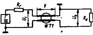
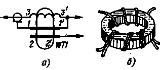
Encyclopedia of radio electronics and electrical engineering / Amateur radio calculations The issues of matching the input impedance of the antenna with the wave impedance of the feeder, as well as balancing antennas for radio amateurs have always been and remain relevant. In recent years, special interest has been shown in transforming and matching devices on ferrite rings. This is due to the fact that such devices can be small-sized and have a high (up to 98%) efficiency. In addition, they do not exhibit resonant properties when the frequency interval is overlapped by several octaves (for example, from 1 to 30 MHz), which is especially convenient when multi-band antennas are used ("squares", "INVERTED V" [1. 2], 3- elemental three-range "wave channel" [3], etc.). In such broadband transformers, the windings are made in the form of two-wire long transmission lines (based on coaxial cable or homogeneous), wound on a ferrite ring. This design of the windings makes it possible to practically eliminate the leakage inductance and reduce the inductance of the leads. The symbol for a transformer on long lines (TLL), adopted in the article, with one winding from a two-wire line is shown in fig. 1.a, with several (in this case, two) - in fig. 1.b.
On fig. 2 shows the inclusion of TDL with a transformation ratio of n=1.
The transformer consists of a winding in the form of a uniform long line wound on an annular ferrite magnetic circuit. Its electrical length is P=2pl/L, where l is the geometric length of the line, L is the wavelength (lambda). Since during the propagation of a high-frequency wave, the currents flowing through the conductors of the line are equal in value and opposite in direction, the magnetic circuit is not magnetized, which means that power is practically not lost in the ferrite. When matching the wave impedance of the line g with the resistances of the source Rg and the load Rl, the TDL theoretically does not have lower and upper boundary -frequencies. In practice, the maximum operating frequency is limited due to lead inductance and line radiation. Attention should be paid to the peculiarity of TDL. which consists in the presence of two types of voltages: anti-phase U, acting between the line conductors and determined by the signal power, and common-mode (or longitudinal) V, due to the asymmetry of the load and depending on the option of switching on the transformer. How the common-mode voltage is formed, acting between the generator and the load, i.e., on the line inductance Ll, is clearly seen from Fig. 3.
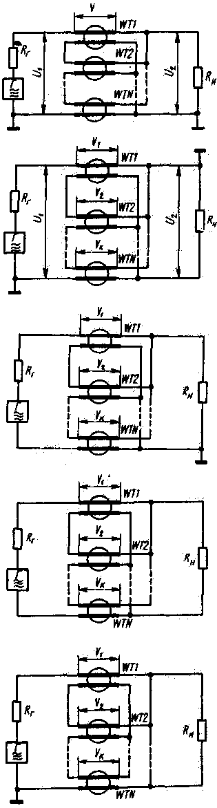
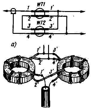
It is obvious that the conductors of a long line shunt the load and the generator if common mode currents flow through them. The introduction of a magnetic circuit sharply increases the inductance of the winding, thereby increasing the resistance to common-mode current and sharply reducing their shunting effect. At the same time, the magnetic circuit does not affect the propagation of the wave, since the traveling wave mode is provided (Rg=g=Ri). There are several ways to construct a TDL with an integer transformation factor n. For example, one can adhere to the following rule. The windings (there must be n) are made of segments of two-wire lines equal in electrical length. Each winding is placed on a separate ring magnetic circuit of the same type. The inputs of the lines from the up side are connected in series, with the down side - in parallel. In general, the switching circuit of a TDL with an integer transformation ratio n is shown in Fig. four.
Here the relations Rg=n2Rn, U1=nU2, g=nRn. On fig. 5 shows various options for switching on the TDL.
It is possible to build a TDL on one magnetic circuit, but the following requirements must be observed. First, the number of turns of each line must be proportional to the value of the common-mode voltage acting between the ends of this line, since the windings are connected by a common magnetic flux. Secondly, the geometric lengths of all lines must necessarily be the same. Depending on the option of switching on the TDL, it may even happen that some lines partially or completely must be placed not on the magnetic core. To determine the number of turns in the windings, it is necessary to calculate the common-mode voltages Vk on each line. In TDL with asymmetric input and output (type NN. Fig. 5, a) Vk \uXNUMXd (n-k) Un; in inverting (type NN, Fig. 5, b) Vk \u1d (n-k + XNUMX) Un; with balanced input and unbalanced output (SN type, Fig. 5, c) Vk \u2d (n / XNUMX-k) Un; with unbalanced input and balanced output (NS type, Fig. 5, d) Vk \u1d (n + 2/XNUMX-k) Un; with symmetrical input and output (type SS, Fig. 5, e) Vk \u2d (n / 2 + t / XNUMX-k) Un. In the formulas, n is the transformation ratio, k is the serial number of the line, counting from above, Un is the voltage at the load. These formulas are the original ones. when the ratio of the number of turns in the windings placed on the magnetic circuit is determined. If, for example, a TDL with a transformation ratio of n=3 is switched on according to the scheme shown in fig. 5, a, then V1:V2:V3=w1:w2:w3=2:1:0. It follows from this that the top line in the figure is placed completely on the magnetic circuit (w1), the second line has only half of the turns (w2 = w1/2), and the third line (w3 = 0) should be completely on the magnetic circuit. The geometric length of all lines is the same. When matching the "wave channel", which has an input impedance of 18,5 Ohm, with a 75-ohm coaxial cable using a TDL (connected according to the circuit in Fig. 5, d) with a transformation ratio of 2, the ratio of winding turns is equal to w1: w2 = (2 + 1 / 2-1: (2 + 1 / 2-2) \u3d 1: XNUMX. This means that on the magnetic circuit the upper winding in the figure should be entirely, and the second - only its third part. When the length of the lines for the windings is much less than the operating wavelength, TDL can be simplified: lines where the common-mode voltages are zero. replaced with a jumper. In this case, for example, a three-winding TDL (Fig. 5, e) is converted into a two-winding one (Fig. 6).
The transmission coefficient of the TDL depends on how much the wave impedance differs from the optimal value and what is the ratio of the electrical length of the line and the wavelength. If, for example, c differs from the required two times, then the losses in the TDL are 0,45 dB for the line length lambda/8 and 2,6 dB for lambda/4. On fig. Figure 7 shows the dependence of the transmission coefficient of a TDL with n=2 on the phase length of its lines for three values of g.
The calculation given in [4] shows that if lines with optimal y values are used, the standing wave ratio in TDL does not exceed 1,03 for line length lambda/16 and 1,2 for line length lambda/8. From this we can conclude that the TDL parameters remain satisfactory when the length of the two-wire lines is less than lambda/8. The initial data for the calculation of TDL are the transformation ratio p, the option of switching on the TDL, the lower and upper limits of the operating frequency range (in hertz), the maximum power Pmax at the load (in watts), the load resistance Rn (in ohms) and the wave impedance of the feeder g (in ohms). The calculation is carried out in the following sequence. 1. Determine the minimum inductance of the line conductor Ll (in henry) from the condition that Ld>>Rg/2fn. In practice, Ll, you can take 5 ... 10 times more than the calculated ratio Rg to 2fn. 2. Find the number of turns w of the line on the ring of the magnetic circuit:
where dcp is the average diameter of the ring (in cm), S - cross-sectional area magnetic core (in cm2), ,u - relative magnetic permeability of the magnetic circuit. 3. Calculate common mode current Ic; (in amperes) flowing through the TDL winding, at the lowest operating frequency: Ic=Vc/2pfnLl, where Vc is the common-mode voltage on the line, calculated for specific switching options in accordance with the above ratios. 4. Determine the magnetic induction (in Tesla) of the magnetic circuit: B=4*10-6.uIC/dcp. The magnetic circuit is chosen taking into account that it is not saturated with common-mode current (or direct current, if any). For this, the magnetic induction in the magnetic circuit must be an order of magnitude less than the saturation induction (taken from reference books). 5. Find the Peak voltage Upeak in the line:
where y is the SWR in the feeder. 6. Calculate the effective value of the current Ieff (in amperes):
7. Determine the diameter d of the wires (in millimeters) of a long line:
where J is the allowable current density (in amperes per millimeter square). For TDL antenna matching devices, ring (sizes K55X32X9, K65X40X9) magnetic cores made of ferrites 300VNS, 200VNS, 90VNS, 50VNS, as well as 400NN, 200NN, 100NN are suitable. If necessary, the magnetic core can be made up of several rings. The required wave impedance of a long line is obtained by evenly twisting the conductors together (with a certain step) (see table). In the case of a cross-shaped connection of wires, c is lower than when adjacent conductors are connected to each other. The wave impedance of a line of non-twisted wires with a diameter of 1.5 mm was 86 Ω. Characteristic impedance of a long line depending on the pitch of the twist and the type of connections
* With a wire diameter of 1 mm. To improve the parameters (in particular, the asymmetry factor) and at the same time simplify the design of the matching-transforming unit, a serial connection of several TDLs of various types is used. For example, using the above method, we calculate the composite TDL with n=2. It must match the input impedance of a 12,5 ohm symmetrical antenna with the RK-50 coaxial cable. The lower operating frequency is 14 MHz. Power does not exceed 200 watts. For TDL, it is supposed to use magnetic cores of size K45X28X8 (dcp=3,65 cm, S=0,7 cm2) from ferrite 100NN (its specific saturation induction is 0,44 T/cm2 [5]). Let the first stage with the transformation ratio n=2 of the composite TDL (Fig. 8) be switched on according to the scheme of Fig. 5, a, and the second (with n = 1) - according to the scheme of Fig. 5, Mr.
We calculate the first TDL. 1. Find Ll:
Let's take Ll equal to 13,5 μH. 2. Calculate the number of turns of the winding:
Such a number of turns of double thick wire can hardly be placed in the window of the magnetic circuit. Therefore, it is advisable to use two rings. In this case, the magnetic circuit will have dimensions K45X 28X16 (S = 1.4 cm2). New number w:
3. Determine the peak voltage at the load:
4. We find the common-mode voltage on the windings in accordance with the switching circuit (Fig. 5, a): V1=(2-1)71=71 V. Since the common-mode voltage on the second winding is 0, this winding is replaced by jumpers (Fig. 6). 5. Common mode current is:
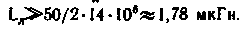
6. We calculate the magnetic induction in the magnetic circuit: H=4*10-6*100*9*0,06/3,65=59*10-6 T, which is much less than the saturation induction. Wave impedance of the line g1=50 Ohm. In the second TDL, it is advisable to use the same rings as in the first. Then Ll \u13,5d 9 μH, w \uXNUMXd XNUMX turns. 7. Common mode voltage on the winding V=(2+1/2-1)71=106,5 V. 8. Common mode current is: L=106,5/2*3,14*14*106* 13,5 * 10-6\u0,09d XNUMX A. 9. Magnetic induction H=100*4*10-6*9*0,09/3,65=89*10-6 Tl. And in this case, it turns out to be less than the saturation induction. The wave resistance of the winding line is chosen about 12 ohms. The diameter of wires for TDL lines is determined in the same way as the diameter of wires for winding in conventional transformers. This calculation is not shown here. An attentive reader may notice an inaccuracy in the above calculation (due to the use of composite TDL). It lies in the fact that the inductance Ll is calculated without taking into account the fact that the TDL windings of the first and second stages are connected, that is, with a certain margin. So in practice, in the TDL of each stage, it is possible to reduce the number of turns in the windings and use smaller ferrite cores. Using combinations of various single TDLs, one can obtain a wide range of TDLs with desired characteristics [4]. For fabricated TDLs, the efficiency and asymmetry coefficient should be measured [4]. The scheme for switching on the TDL when determining the first parameter is shown in fig. 9, the second - in Fig. 10. Losses a (in decibels) in the transformer are calculated by the formula: a \u20d 1lg (U2 / nUXNUMX).
Several TDLs were made by the author. The practical data of some of them are given below. The appearance of two transformers is shown in fig. eleven.
Balancing TDL (type NS) with a transformation ratio n = 1, operating in the frequency range of 1,5 ... 30 MHz with an output power of up to 200 W, to match the RK-50 feeder with an antenna input impedance of 50 Ohm, it can be made on a 50VNS magnetic circuit with a standard size K65X40X9. The number of turns of the windings of the line (g \u50d 9 Ohm) is 1. Windings 1-2 ', 2-12' (Fig. 2) are wound into 2 wires PEV-1,4 3 bifilarly, without twists. To ensure the constancy of the distance between the wires, they are put on a fluoroplastic tube. The winding 3-1' is wound separately on the free part of the ring with the same wire and the same length as the windings 1-2', 2-98'. The efficiency of the manufactured TDL was about 300%. asymmetry coefficient - more than XNUMX.
TDL with a transformation ratio n=2 (NS type), designed for power up to 200 W, matching the 75-ohm feeder impedance with a symmetrical antenna input, which has an input impedance of 18 ohms. can be made on a 200NN magnetic circuit (Fig. 13) with a size K65X40X9. The windings must contain 9 turns of lines from PEV-2.1,0 wires. The manufactured transformer had an efficiency of 97%, asymmetry coefficient at a frequency of 10 MHz - 20, at a frequency of 30 MHz - at least 60.
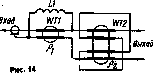
On fig. 14 shows the connection diagram of a composite TDL (NS type) with a transformation ratio of n=3, matching an antenna with an input impedance of 9 ohms, with a 75-ohm coaxial cable. TDL, designed to operate in the range of 10 ... 30 MHz at a power of up to 200 W, is performed on rings (size K32X20X6) of 50VNS ferrite. The magnetic circuits of transformers WT1 and WT2 are made up of two rings, the windings and coil L1 must contain 6 turns each. Long lines and a coil are made with PEV-2 1,0 wire. Line impedance for WT1 - 70 Ohm, for WT2 - 25 Ohm. The constructed TDL had an efficiency of 97%, the asymmetry coefficient was at least 250.
Before operating the TDL, measures should be taken to protect them from adverse climatic influences. To do this, the transformers are wrapped with fluoroplastic tape, placed in a box and, if possible, filled with KLT compound. Literature: 1. Benkovsky 3., Livisky E. Amateur antennas of short and ultrashort waves. - M .; Radio and communications, 1983. Author: V. Zakharov (UA3FU), Moscow; Publication: N. Bolshakov, rf.atnn.ru
Air trap for insects
01.05.2024 The threat of space debris to the Earth's magnetic field
01.05.2024 Solidification of bulk substances
30.04.2024
▪ A new way of skin rejuvenation
▪ section of the site Electricity for beginners. Article selection ▪ article Gray cardinal. Popular expression ▪ article Which animals contain natural sunblock in their bodies? Detailed answer ▪ Japanese kelp article. Legends, cultivation, methods of application ▪ article Miscellaneous electronic devices. Directory ▪ article Thyristor charging unit. Encyclopedia of radio electronics and electrical engineering
Comments on the article: Alexander Kompromister, alexgr123@yandex.ru How can I contact the author of this article?
Home page | Library | Articles | Website map | Site Reviews
www.diagram.com.ua | |||||||||||||||||||||||||||||||||||


 Leave your comment on this article: