|
|


 Arabic
 Bengali
 Chinese
 English
 French
 German
 Hebrew
 Hindi
Hindi Italian
 Japanese
 Korean
 Malay
Malay Polish
 Portuguese
 Spanish
 Turkish
 Ukrainian
 Vietnamese
|
ENCYCLOPEDIA OF RADIO ELECTRONICS AND ELECTRICAL ENGINEERING Surge protection device. Encyclopedia of radio electronics and electrical engineering
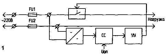
Encyclopedia of radio electronics and electrical engineering / Protection of equipment from emergency operation of the network In [1], a device is described that turns off the primary winding of the mains transformer by heating the temperature sensor when the mains voltage rises. In my opinion, this design has a number of disadvantages: - limited application. It cannot be used to protect such expensive household appliances as a refrigerator, washing machine, TV; - large inertia of the sensor, depending on the distance from the place of its attachment to the transformer housing. I offer my own version of a device that protects the network throughout the room. The device, the block diagram of which is shown in Fig. 1, consists of a rectifier; a comparison circuit that registers an increase in voltage in the network; control devices and keys.
The schematic diagram of the device is shown in Fig.2. The sensor is an unstabilized DC voltage source, consisting of a transformer T1, a diode bridge VD4 and a capacitor C4.
When the voltage in the network increases, the voltage at the output of the VD4 bridge increases. At a certain value of this voltage, the comparator DA1 is activated. The output signal of the comparator is fed to the input of the generator (DD1.1, DD1.2) of the control device, described in detail in [3]. The RS-trigger is excluded from the device, because the generator is controlled by the comparator DA1. The switching element (key) is a triac VS1 connected to the generator. The generator generates pulses with a frequency of 10 kHz with a duty cycle of 10. The maximum duty cycle of the pulses is limited only by the time the triac is turned on. For KU208G, the duration of the control pulse must be at least 10 µs. The control unit includes a power source assembled on the elements VD1, VD2, C1, R1, R2. Transistor VT2 - generator pulse power amplifier. A high level from the output of the comparator starts the pulse generator. At the moment of startup, the device consumes more current, which at the first moment is maintained by the voltage on the capacitor C1. Then the triac VS1 opens and, through the resistor R7, the transistor VT1. Open transistor VT1 shunts resistor R2, thereby providing even more supply current. LED HL1 is used to indicate the inclusion of the load. The operation of the comparator DA1 is described in detail in [2]. The reference voltage applied to pin 5 sets the upper threshold. The value of the hysteresis of the transfer characteristic
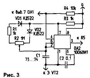
where R9' is the resistance of the upper part according to the scheme (before the engine) of the resistor R9; R9 "is the resistance of the lower part (from the engine) of the resistor R9 according to the circuit. When the input signal reaches the upper threshold of the comparator, i.e. Uop. The logical "1" voltage is set at the DA0 output. The generator turns off, the thyristor VS1 remains closed, and the load is disconnected from the network.If after that the input voltage decreases relative to Uon by the value Ug, then the output level is again set to "1", and the load is connected to the network.The value of the hysteresis, and hence the lower threshold of the comparator, is regulated by resistor R9. Details and design. Transformer T1 must be designed for a primary winding voltage of 380 ... 400 V. It can be either ready-made or modified. The refinement consists in winding an additional number of turns of the primary winding, corresponding to 380 V. The secondary winding of the transformer must be designed for a voltage of 4 ... 5 V at the rated mains voltage (220 V). A stabilizer of any design can serve as a source of reference voltage Uo„ for comparator DA1 (it is not shown in the diagram). Capacitor C3 suppresses possible radio interference and improves the shape of the output voltage. It must have an operating voltage of at least 500 V. Setting up the device comes down to setting the threshold for the operation of the comparator DA1 and selecting the value of the resistor R6 for reliable operation of the triac VS1. To set the response threshold of the comparator DA1, a voltage is applied to the input of the device through the LATR within the tolerance of the network - usually not higher than 240 ... 245 V. After that, the voltage value on the capacitor C4 is measured. A voltage of the same magnitude is applied to pin 5 of DA1 and is Uon. Then, by reducing the input voltage, the resistor R9 sets the desired threshold for turning on the comparator. Due to the relative complexity of manufacturing the transformer T1, it is possible to apply a transformerless comparator circuit, which is described in detail in [4]. In the proposed variants of the IC DD1 is not fully used (there are free elements). To eliminate this drawback, I propose to replace the generator on the IC DD1 with a generator according to the circuit shown in Fig. 3 [5].
Generator Oscillation Period T=R2 • C1 • /p2. The generator is controlled by the blocking input (pin 4) from the pin 7 of the DA1 comparator (Fig. 2). When the level of logic "1" at the blocking input (pin 4), the blocking of the timer is disabled. When a logical "0" is applied, the blocking is enabled, and the timer goes from any active state to a passive (off), i.e. generation is interrupted. Fuses FU1, FU2 in Fig. 1 and Fig. 2 are residential fuses ("plugs"). It is advisable to install the KU208 triac on a heat sink. Instead of a triac, two KU202 thyristors can be used, turning them on in anti-parallel to increase the switched power. Capacitor C1 must have a minimum leakage current. If it is necessary to increase the power supplied by the power supply, the values of the resistors R1 and R2 are reduced, and the value of the capacitor C1 is increased. Literature 1. Milyushin A. Device for thermal protection of electronic clocks. - Radio amateur, 1998, No. 4, S. 30. Author: A. Ilyin, St. Petersburg; Publication: N. Bolshakov, rf.atnn.ru
Machine for thinning flowers in gardens
02.05.2024 Advanced Infrared Microscope
02.05.2024 Air trap for insects
01.05.2024
▪ Ice cubes control drinking alcohol ▪ A transistor that can be dissolved by sound and water ▪ New ways of liver regeneration have been found ▪ Women are more sensitive to stress than men
▪ site section Power supply. Article selection ▪ Article Lighting fixtures. video art ▪ How far does space extend? Detailed answer ▪ Lilac article. Legends, cultivation, methods of application
Home page | Library | Articles | Website map | Site Reviews
www.diagram.com.ua |


 Leave your comment on this article: