|
|


 Arabic
 Bengali
 Chinese
 English
 French
 German
 Hebrew
 Hindi
Hindi Italian
 Japanese
 Korean
 Malay
Malay Polish
 Portuguese
 Spanish
 Turkish
 Ukrainian
 Vietnamese
|
ENCYCLOPEDIA OF RADIO ELECTRONICS AND ELECTRICAL ENGINEERING Loudspeakers with dipole radiators. Encyclopedia of radio electronics and electrical engineering
Encyclopedia of radio electronics and electrical engineering / Speakers The author proposed an original design of speakers with dipole emitters. The design of the acoustic design of dynamic heads, intended mainly for automotive speakers, is made of plastic pipes. It is also acceptable to use cardboard or papier-mâché pipes of sufficient thickness and a suitable diameter. To set up and check the parameters of the manufactured AS, the author used the SpectraLab computer program. Articles published recently in the journal "Radio" show that the level of development of audiophile speaker systems has risen to a new level. Obviously, this is not least due to the availability of higher quality heads. Nowadays, the most common on sale are dynamic heads for car speakers of various capacities, which provide a fairly high sound quality. The acoustic system described in the article can be made with dynamic heads available to the amateur, and the use of ready-made sets of heads for car speakers greatly simplifies their choice. The purpose of developing this design was the desire to produce a speaker system with good sound and original design; besides, it was interesting to listen to different variants of the acoustic design of the heads. In particular, it was supposed to compare the special sounding of bipolar and dipole loudspeakers, which differ in the radiation pattern and phase characteristic of the radiation (more on the features of their work - further in the text). As a result of the analysis of the structure of various speakers (bipolar "Mirage" [1], dipole "Alon" manufactured by ACARIAN SYSTEMS, etc.), the author developed the design of the speakers described here. The acoustic system enclosures (Fig. 1) are made of a polyethylene pipe with an outer diameter of 160 mm and a wall thickness of 9 mm. AC loudspeakers - three-way; each consists of three separate boxes combined in one design. The bass driver is installed horizontally in the upper end plane of the main box. Its internal volume from below (up to the phase inverter pipes, brought out to the rear side of the case) is filled with a low-density padding polyester, and above the pipes there are two rings of dense foam rubber 5 cm wide, which reduce standing waves in the case. The distance between the rings is about 50 cm.
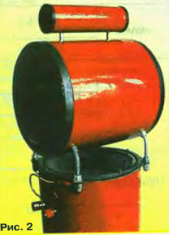
The midrange box installed above the woofer head simultaneously serves as a "diffuser" for the woofer emitter. This box is made from a piece of a similar pipe. The internal volume is filled with a three-layer stuffing of medium density (synthetic winterizer-cotton wool-synthetic winterizer). From the end sides, identical plastic head holders with removable protective nets are attached to it (with glue or screws). duralumin bracket 2 ... 3 mm thick with the necessary protrusions), and through the walls of the upper block. The height of the box fastening is regulated by curly or ordinary nuts. The HF box is made of a piece of polyethylene pipe with a diameter of 40 mm and is mounted on two decorative pins, creating a gap between the boxes of about 15 mm. The HF heads are installed on both sides of the pipe section and are fixed only with a tight fit. The appearance of the speakers - in fig. 2.
Pipes of the desired diameter can be made from papier-mâché using the method described in "Radio" [2], as well as selected from commercially available pipes for various purposes. As a last resort, you can make rectangular, square-section enclosures from chipboard or MDF (compressed wood dust board). Three types of dynamic heads are used in the design (the loudspeaker diagram is shown in Fig. 3). For the low-frequency band (BA5) - Kenwood KW-160-1374 head with Thiel-Small parameters (TS): resonant frequency Fs= 45 Hz, total Q factor Qts= 0,5...0,55. In the MF band (VAZ, VA4), P130LU15-08-4 heads of the Ryazan Radio Plant with a resonance frequency Fs = 75 Hz and a sensitivity of 89 dB were used [3]. In the HF band (BA1, BA2), LANZAR heads (for car audio) were used: the effective radiation band is 1 ... 24 kHz, the sensitivity is 94 dB and the characteristic of complex impedance is almost flat, without visible resonance. In these heads, the dome is made of titanium, and a ferromagnetic fluid is introduced into the magnetic gap.
Heads MF, HF can be used and others - from component automotive speakers from various manufacturers. It is undesirable to use heads with a built-in additional HF horn. Compact woofers of sufficient power with a diameter of 6 to 6,5 inches are probably also easier to find among those designed for car speakers. It is acceptable to use other available "woofers", but then the fastening of the bass head and midrange box may have to be changed. The calculated dimensions of the cabinet with a phase inverter for the bass head used turned out to be unacceptably large (volume Vb, = 42 l), so the dimensions and lower frequency of the playback band were adjusted for a cabinet with a smaller volume. Two phase inverter pipes are used to reduce the length of the resonator with the calculated cross-sectional area. The resonator resonator was tuned without a low-pass filter in order to best reproduce the sound of low frequencies while maintaining a clear sound in the mid-frequency region. Then the characteristic of the complex resistance was checked, which showed the equality of the characteristic maxima and the tuning frequency of the pipe Fb = 42 Hz. If domestic LF heads are used in the AU, then the parameters of the structural elements (case volume, phase inverter pipe dimensions, etc.) can be found in [4] and in descriptions of designs with similar heads. In this design, filters of the second (for the bass head) and first (for the midrange, high-frequency heads) orders are used. For filters of the 3rd order (MF and HF), it turned out to be difficult to obtain a consistent sound and an acceptable phase response of the complex impedance in the selected acoustic design. In the manufacture of filters, the author used capacitors K73-17 with a capacity of 4.7 μF at 63 V, oxide capacitors with a capacity of 100 and 47 μF from Jamicon (non-polar NP groups). Coil L1 has 110 turns and is wound with PEL wire 0,72 mm without a frame on a mandrel with a diameter of 20 mm with a winding width of 10 mm. To reduce losses, the L2 coil (100 turns of PEL wire 0,9) is made with a magnetic circuit from a package of W-shaped plates with a cross section of 3,5 ... 4 cm2 (without jumpers) and is wound on the frame of an UHF transformer of an old TV. The inductance of the coil L2 is selected by winding part of the turns. The "SpectraLab" program [5] and a simple set-top box connected to the computer's sound card (Fig. 4) can provide invaluable assistance in measuring all the parameters of the heads and the system. Using such a device, one can observe the frequency response and phase response of the complex resistance directly in the process of measuring the parameters of the heads, tuning the phase inverter resonator and filters.
In the program, in the "Settings" section, you need to set the view mode of the voltage division quotient at the input of the right channel to the analogous one of the left channel (or vice versa), and also enable the linear input of the card in the "Record" mode. As a result, on the screen we will see the frequency response and phase response of the studied quadripole. The sound card of the computer must be full duplex, i.e., allowing simultaneous operation with its input and output. In all modes, you need to enable the built-in pink noise generator from the "Utilities" section (for more information, see the "help" section of the program). By switching the program to the spectrum view mode and selecting the microphone input of the sound card, you can measure the frequency response and phase response of the head (system) by sound pressure with an accuracy determined by the quality of the microphone. The frequency response of electret microphones for computers is linear enough to assess the unevenness of the frequency response of heads and speakers, in addition, the program has the ability to compensate for the non-linearity of the frequency response of the microphone used. For acoustic measurements, a YOGA EM-195 microphone with a sensitivity of 64 ± 3 dB (1 dB = 1 V/μbar at 20 kHz) and a band of 16000...XNUMX Hz was used. In the manufacture of filters for this speaker system, the main difficulties were caused by matching the midrange and tweeters, and as a result, the simplest solution turned out to be the most effective. For the heads used in the design, filters of the second and first orders made it possible to obtain a smooth frequency response. On fig. Figure 5 shows the frequency response of the loudspeaker presented by the "SpectraLab" program, taken with the microphone installed on the radiation axis of 0 degrees (upper curve) and at an angle of 90 degrees (lower curve).
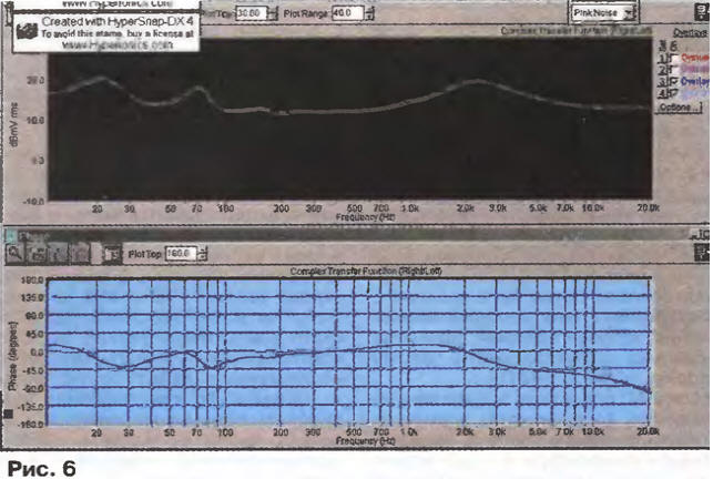
The frequency response of the loudspeaker complex impedance module, shown in fig. 6, changes smoothly in the range of 3,8 ... 8 ohms. Deviations in the linearity of the PFC do not go beyond ±45 degrees. It should be noted that the sound card used for measurement has a drop in PFC above a frequency of 10 kHz to -90 deg. Therefore, before measuring, it is necessary to calibrate the measuring path by connecting a variable resistor instead of the head (with an adjustable resistance scale). At the same time, it can be used to measure the complex resistance of the AC.
When listening to the manufactured speaker system, two options for turning on the heads in the midrange and treble boxes were tested. The first option is when the front and rear heads are turned on (taking into account their physical location) out of phase. In this case, the resulting radiation characteristic can be considered as bipolar (radiation forward and backward in phase). Its frequency response (not shown in the article) is equally flat in the positions of 0 and 90 degrees. At low frequencies (below 300 Hz), waviness appears, but this does not spoil the sound. The sound acquires a greater "volume" in comparison with a conventional loudspeaker. The greatest effect is achieved when the distance between the speakers is more than 3 ... 4 m. For example, when the speakers are installed at the diagonal corners of the room, the stereo balance is achieved by the corresponding control in the amplifier, providing a comfortable sound for home cinema, light music, and computer games. The second option for switching on is when the heads are switched on in phase. As a result, we get a dipole speaker system, the radiation pattern of which can be defined as a "figure eight", since side radiation in the MF-HF range is suppressed. In reality, this effect manifested itself insignificantly: the frequency response when the microphone was installed on the side, at 90 degrees, was also flat, as for the axial one (0 degrees), but with a smooth decrease in the sound pressure level at midrange and treble (see Fig. 5). Such inclusion of the heads can be considered as isobaric, which does not increase the resonant frequency of the heads in the acoustic design and additionally reduces the even harmonics. In this case, the sound, together with the volume, acquired greater accuracy in the development of the sound stage and distinctness; this option was preferred by the author. In both cases, the sound is qualitatively different from the usual depth of the scene and its construction, and a slight dependence of the tonal balance on the listening place. This allows you to move around the room both in front of the "sound stage" and directly inside it, in contrast to the usual rather narrow stereo effect zone. AU loudspeakers should be at least 40 ... 50 cm away from the nearest sound-reflecting surfaces, and these surfaces themselves, if possible, are covered with absorbing materials (for example, curtains). In a Dolby Surround ProLogic multi-channel home theater system, to create a diffuse field that transmits an acoustic atmosphere, the Nome THX licensing program recommends using dipole drivers as rear speakers, which should be oriented to listeners not with the front or rear lobe, but with "zero" . Literature
Author: S. Alikov, Moscow
Artificial leather for touch emulation
15.04.2024 Petgugu Global cat litter
15.04.2024 The attractiveness of caring men
14.04.2024
▪ The science of petting a cat ▪ Dancing helps in the study of the exact sciences ▪ Old people benefit from computer games ▪ Apple TV
▪ section of the site Factory technology at home. Article selection ▪ article Sorcerer's Apprentice. Popular expression ▪ How is the situation in post-war China? Detailed answer ▪ Wi-Fi Basics article. Encyclopedia of radio electronics and electrical engineering
Home page | Library | Articles | Website map | Site Reviews
www.diagram.com.ua |


 Leave your comment on this article: