|
|


 Arabic
 Bengali
 Chinese
 English
 French
 German
 Hebrew
 Hindi
Hindi Italian
 Japanese
 Korean
 Malay
Malay Polish
 Portuguese
 Spanish
 Turkish
 Ukrainian
 Vietnamese
|
ENCYCLOPEDIA OF RADIO ELECTRONICS AND ELECTRICAL ENGINEERING Frequency synthesizer for a radio station in the range of 144 ... 146 MHz. Encyclopedia of radio electronics and electrical engineering
Encyclopedia of radio electronics and electrical engineering / Frequency synthesizers At present, the industry has mastered the production of a microchip of a single-chip frequency synthesizer built according to the prescaler scheme. This K1508PL1 chip is made using CMOS technology in a planar 14-pin package. The division coefficients are loaded into the control register of the microcircuit in a serial code. The microcircuit contains in its composition a frequency divider with a fixed division ratio (DFKD) and a frequency divider with a variable division ratio (CVD). The input is made through pin 4 of the microcircuit. The code has a length of 19 digits (Table 1), and the digits F0...F15 determine the division factor of the DPCD, and the digits R0...R2 - the division factor of the DPCD. Table 1 Distribution of the contents of the control code in the register
The DPCD division coefficients that can be set in this microcircuit are shown in Table 2. Table 2
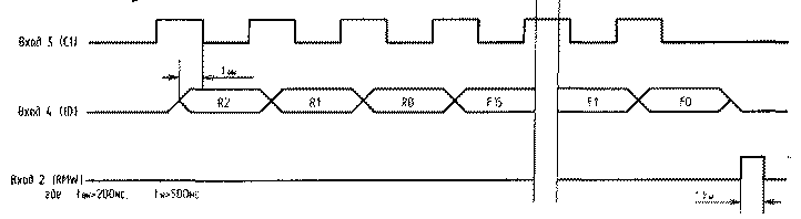
The timing diagram for loading the division coefficients into the control register of the microcircuit is shown in Fig. 1. For example, let's find the synthesizer control code for the case: Fvco = 145 MHz - the main frequency of the voltage-controlled oscillator (VCO a); Fkv \u10d 2 MHz - the frequency of the quartz resonator; FDIV12,5=XNUMX kHz - comparison frequency (tuning discrete). Then: N1=Fкв/FDIV2=10 МГц/12,5 кГц=800.
At the input of the D1 - 10 (VCO) microcircuit, it is necessary to supply voltage from a voltage-controlled generator (VCO) with a level of at least 1 V. Schematic diagram of the frequency synthesizer. Fig.2 The comparison frequency is chosen equal to 12,5 kHz and is equal to the synthesizer tuning interval over the range. Thus, the entire range of 144 - 146 MHz is divided into 160 discrete frequencies or channels. The D1 chip of the K1508PL1 type is loaded through pins 2, 3,4 as described above. Quartz resonator ZQ1 - at a frequency of 10 MHz. Capacitor C3 serves to fine-tune the comparison frequency. A signal with frequencies up to 10 MHz can be applied to the input 200 of the microcircuit, and at an input frequency of 200 MHz, its amplitude can decrease from 1 V to 100 mV. At the output of the phase detector of the D1 microcircuit, diodes VD1 and VD2 are included to reduce non-linear distortion during frequency modulation. The linear integrating filter on the elements R7, C5, C4 determines the time for tuning the synthesizer from one frequency to another. It is about 50 ms. On the transistor VT1, the diode VD4, the LED HL1 of the AL307BM type, an indicator of the capture of the phase-locked loop (PLL) capture ring is built. Transistor VT1 - type KT315B. When the PLL is locked, the LED goes out. From the linear integrating filter, the frequency mismatch voltage is applied to the VD3 varicap of the KV109G type. The VCO is built on a VT2 transistor of the KT325B type according to a common base circuit. Such a circuit is more broadband and produces a larger signal amplitude compared to the common emitter circuit. The VCO buffer amplifier for the DA1 chip is built on a resistive amplifier based on a VT4 transistor of the KT325B type. The modulating voltage on the VD3 varicap is supplied through pin 4 of the board. The output voltage of the synthesizer to the receiver and power amplifier of the radio station is taken from the source of the transistor VT3 of the KP307G type. Schematic diagram of the frequency synthesizer controller. Fig.3 It is built on a K1830BE31 type microprocessor, also made using CMOS technology. The controller keyboard contains 16 buttons S1...S16, which set the channel number from 0 to 160 by first pressing the "channel" - "K" button. The "<-" and "->" buttons are used to shift one channel lower or higher in frequency. If you hold these buttons for a long time, you will quickly tune through the channels. When you press the "CK" button, the channels are scanned, starting from the set and higher in frequency. The scanning process is circular. On each channel, the synthesizer is delayed for 5 seconds. Pressing any of the buttons again stops scanning on the channel set at the current time. The controller has the ability to record up to 10 selected channels by pressing the "P" button. Pressing the "P" button - after each set of memorized channel. In this case, the dialed channels are assigned numbers from 0 to 9. To now set one of the pre-prepared channels, you just need to press one of the buttons with the corresponding number. To change the prepared channel, you must press the button with a different number. The "SKP" button allows you to scan pre-selected channels. At the time of recording the channel number, the HL2 "Record" LED of the AL307BM type lights up. The channel number indicator is built on LED matrices HG1... HG3 type ALS324A. If the keyboard is not pressed for 3 minutes, the indication is extinguished by turning off registers D7, D8 and indicators HG1 ... HG3 as the most energy-consuming using a key on a VT1 transistor of the KT815B type. At the same time, the LED HL1 "Work" of the AL307BM type lights up. The controller keyboard works on interrupts at the INTO input of the D1 chip. Switching "reception-transmission" is carried out using the interrupt INT1, while the port P1 of the D1 chip is switched to the input mode and the discharge of the port P1.6 is polled. While a low logic level is being registered on it by the controller, the transmission frequency code of the selected channel is written to the control register of the frequency synthesizer. The reception frequency in this synthesizer is set after releasing the "reception-transmission" key. This key is connected via pin 7 of the controller. This synthesizer is designed to work with radio stations in which the first intermediate frequency is 10,7 MHz. You can also choose another intermediate frequency, but in this case you will have to rewrite some memory cells of the controller's ROM. Through pins 1,2,3 of the board, the frequency code from the controller is fed to the synthesizer board. If the radio amateur does not have this microprocessor, the controller can be built on a microprocessor of another series or performed on "hard" logic, as was done in the article in "RL" No. 10, 1993. The connection diagram of the synthesizer and controller boards is shown in Fig. 4.
Voltage stabilizers for + 5V and + 9V are built on D1 type KR142EN5A and D2 type KR142EN8A chips, respectively. The synthesizer is powered by a +12V power supply. Structurally, the frequency synthesizer is made on two printed circuit boards made of double-sided foil fiberglass. It is necessary to carry out a good shielding of both boards. Coil L1 of the synthesizer is wound on a frame made of organic glass with a diameter of 5 mm and contains 30 turns of PEV-2 wire with a diameter of 0,15 mm, wound round to round. The L2 coil is frameless and has 4 turns of PSR-0,8 wire wound on a mandrel with a diameter of 5 mm, the winding length is 8 mm. Synthesizer setup starts with the controller. With proper installation and serviceable components, as well as with a correctly programmed ROM, the controller does not require configuration. By connecting the controller to the synthesizer, the frequency is set to 145 MHz, which corresponds to channel number 80, and by rotating the rotor of the capacitor C6, a voltage is achieved At the point of its connection with the VD3 varicap and the resistor R8 - 3 V. e. in the transmission mode, then release the "reception-transmission" key, while the output of the synthesizer should be set to a frequency of 134,3 MHz. Frequency control is carried out by a digital frequency meter at terminal 6 of the synthesizer board. If necessary, compress or. stretch the turns of the coil L2. Then a modulating voltage is applied to terminal 4 of the synthesizer board with a frequency of 1 kHz and an amplitude of 250 mV. Resistor R13 sets the frequency deviation equal to 3 kHz. The control is carried out with a frequency deviation meter of the SKZ-43 type or any other. You can also set the deviation for the existing FM receiver at 144 ... 146 MHz for the loudest and clearest signal. The deviation meter is connected to output 6 of the synthesizer board. The deviation is set when the "reception-transmission" key is pressed, i.e. in transmission mode. By rotating the rotor of the capacitor C3 and the core of the coil L1, the reference frequency is set exactly to 12,5 kHz. This completes the tuning of the frequency synthesizer. For purchase of printed circuit board drawings, a set of documentation, ROM firmware, as well as synthesizer and processor microcircuits, please contact the author. Author: V. Stasenko (RA3QEJ), Rossosh, Voronezh region; Publication: N. Bolshakov, rf.atnn.ru
Artificial leather for touch emulation
15.04.2024 Petgugu Global cat litter
15.04.2024 The attractiveness of caring men
14.04.2024
▪ Babies are resistant to visual illusions ▪ A camera with a resolution of 1 GPU has been developed ▪ The science of petting a cat ▪ Samsung Class Terrace Full Sun Neo QLED 4K Waterproof Outdoor TV
▪ section of the site Audio and video surveillance. Selection of articles ▪ article Facts are stubborn things. Popular expression ▪ article Where and when was the first World Cup held? Detailed answer ▪ article Electrobrush. home workshop ▪ article Safe charger. Encyclopedia of radio electronics and electrical engineering
Home page | Library | Articles | Website map | Site Reviews
www.diagram.com.ua | |||||||||||||||||||||||||||||||||||||||||||||||||||||||||||||||||||||||||||||||||||||||||||||||||||||||||||||||||||||||||||||


 Leave your comment on this article: