|
|
ENCYCLOPEDIA OF RADIO ELECTRONICS AND ELECTRICAL ENGINEERING VHF FM radio station. Encyclopedia of radio electronics and electrical engineering
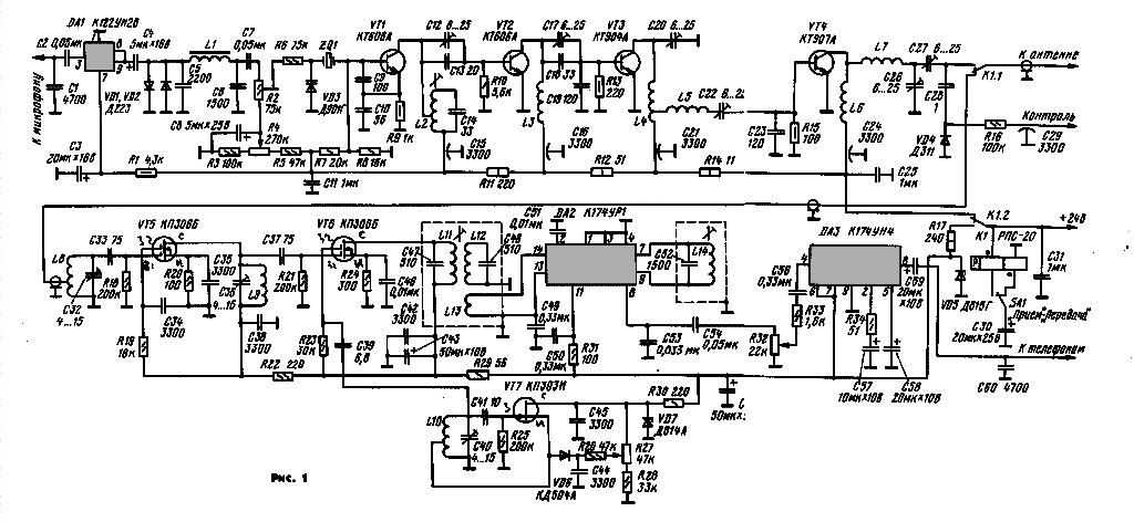
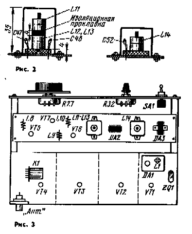
Encyclopedia of radio electronics and electrical engineering / Civil radio communications Amateur communications on the VHF bands using frequency (FM) or phase (PM) modulation in our country is still developing very slowly, despite a number of publications that have appeared in Radio in recent years. One of the reasons is the lack of a description of a simple radio station available for repetition by a wide range of radio amateurs. This article attempts to fill this gap. First, a few words about the main ideas embodied in this development. At present, the frequency stability requirements for VHF transmitters are such that it is necessary to use quartz stabilization. It is such a transmitter with the frequency multiplication of the master oscillator that is used in the radio station. This, however, excludes the tuning of its frequency within a significant range, but it turns out to be quite simple. Modern microcircuits allow a simple receiver to be assembled according to a superheterodyne circuit with one frequency conversion. If a local oscillator with quartz stabilization and its subsequent multiplication is used in the receiver, then it becomes necessary to select two quartz resonators with a precisely specified frequency difference. ^In addition, the receiver will be single-channel, with a very limited possibility of its frequency tuning. Therefore, it was decided to use a continuously tunable LC local oscillator, which made it possible to listen to the entire range of 144 ... 146 MHz and work with other radio stations that differ in the transmitter frequency, i.e., at spaced frequencies. The receiver circuit is even more simplified. The transmitter and receiver of this radio station are completely independent, which makes it possible not only to manufacture and configure them separately, but also to listen to your own signal while on the air. Consider the schematic diagram of the radio station (Fig. 1). The microphone amplifier of the transmitter of the radio station is made on a DAI chip loaded with a diode limiter (VDI, VD2), which allows increasing the average modulation index, and hence its efficiency, and at the same time avoiding overmodulation and excessive expansion of the emission spectrum at the peaks of the audio signal. A significant part of the harmonics of the limited audio signal is attenuated by the LIC5C6 U-shaped low-pass filter with a cutoff frequency of 3 kHz. The filtered audio signal is fed to the VD3 varicap connected in series with the quartz resonator in the master oscillator. The constant bias voltage on the varicap is regulated by a variable resistor R4, while the output frequency of the transmitter is tuned within a small range (10 ... 20 kHz). The required modulation index (1,5 ... 2) is set by resistor R2. In this case, the frequency deviation will be 5 ... 7 kHz. The master oscillator is assembled according to a three-point circuit with capacitive feedback (capacitors C9, CIO) on a transistor VT1. The quartz resonator is excited at the fundamental frequency, which is in the range of 9...9,12 MHz. You can also use resonators for frequencies of 12 ... 12.17 MHz and 18 ... 18,25 MHz. High-frequency crystals are even preferable, since the shorter frequency multiplication improves the spectral purity of the output signal. The L2C14 circuit is tuned to 36 MHz. In order to increase its loaded quality factor, and hence to improve the filtering of adjacent harmonics, an incomplete autotransformer inclusion of the circuit in the collector circuit was applied. A signal with a frequency of 36 MHz through coupling capacitors C12, C13 is fed to a frequency doubler assembled on a transistor VT2. Trimmer capacitor C12 can adjust the signal transmitted to subsequent nodes. Bias to the doubler, as well as to subsequent stages, is not applied. At the same time, transistors operate in class C mode, providing high frequency multiplication efficiency and high efficiency in amplification mode. The L3C17C18C19 circuit is tuned to 72 MHz. Another frequency doubler is assembled on a VT3 transistor. Its collector circuit emits a 144 MHz signal. For better filtration, a two-circuit circuit is used here. From the tap of the coil of the first circuit L4C20, the signal comes to the second circuit L5C22C23, which also serves to match the input of the power amplifier, made on the transistor VT4. The output power is about 2,5 W with a total current consumption in the power supply circuit of 300 mA. The output circuit of the transmitter is formed by coils L6, L7 and tuning capacitors C26, C27, with which it is tuned to resonance and matched with the antenna. The output impedance of the transmitter is within 50...75 0m. To switch the antenna feeder from the transmitter to the receiver and the power circuit, a remote switch K 1 is used. To control it, a short current pulse is applied to one or the other winding. It is formed when the capacitor C3O is charged and discharged. You can also use a relay connected according to the traditional scheme. It is desirable that its contacts have a low capacitance and a short length of internal connecting conductors. The radio receiver is assembled according to the usual superheterodyne circuit. The IF value of 2,3 MHz was chosen in such a way as to significantly attenuate the image channel by the input circuits, and at the same time not to expand the IF bandwidth too much (as you know, with an increase in the IF value, the selectivity for the image channel increases, but the bandwidth from - due to the limited constructive quality factor of the circuits). The signal from switch K1 is fed to the input circuit L8C32 of a radio frequency amplifier assembled on a double-gate field-effect transistor VT5, which provides high input impedance and stable signal amplification. The mixer uses a VT6 transistor of the same type. The amplified RF signal from the L9C36 circuit is applied to the first gate, and the local oscillator voltage is applied to the second. The receiver local oscillator is made according to the inductive three-point circuit on a VT7 field-effect transistor. For frequency tuning, a VD10 diode, used as a varicap, is connected to the tap of the local oscillator coil L6. By adjusting the bias voltage on it with a variable resistor R27, you can change its capacitance, and hence the frequency of the local oscillator. The LIIC47L12C48 dual-loop bandpass filter selects the 2,3 MHz IF signal, which is fed through the L13 coupling coil to the input of the DA2 microcircuit. It consists of an IF amplifier, a limiter and a frequency detector. The phase-shifting circuit of the L14C52 detector is set to IF 2,3 MHz. The detected sound signal through the volume control R32 is fed to the amplifier 34, made on the DA3 chip, and then to the telephones or loudspeaker. Parts of the radio station can be of various types, but some requirements that are common to any U KB devices must be observed. So, in high-frequency circuits, only ceramic capacitors can be used. The length of their conclusions should be shortened to the minimum possible. Feed-through blocking capacitors can have any capacitance from several thousand picofarads or more. Trimmer capacitors - K.PK or KPKM. Capacitors of any type can be used in the IF path and 34 of the receiver. All fixed resistors in the receiver are MLT, variables are of any type. The secondary (step-up) winding of a small-sized TOT1 transformer, which has an inductance of about 7 H, was used as a low-pass filter coil L3. You can also use the primary winding of the matching transformer from the amplifier 34 portable receivers. Coil L2 is wound on a cylindrical frame with a diameter of 8 mm and contains 7 turns of PEL 0,5 wire. Winding ordinary. The tap is made from the 3rd turn, counting from the output connected to the capacitor C15, Trimmer - magnetite, SCR. The rest of the transmitter coils are frameless. They are made on a mandrel with a diameter of 10 mm with bare copper wire with a diameter of l..1,2 mm. It is good (but not necessary) to use silver-plated wire. Coils L3 and L6 contain 4 turns each with a winding length of 15 mm, L4, L5 and L7 - 3 turns each with a winding length of 8 ... 10 mm. The tap from the coil L4 is made from the first turn, counting from the output connected to the capacitor C21. The receiver coils L8 and L9 are also frameless, but wound on a mandrel with a diameter of 4 mm with PEL wire 0,7 ... 0,8. Coil L8 contains 5 turns with a winding length of 9 mm with a tap from the second turn, L9 - 4 turns with a winding length of 7 mm. The local oscillator coil L10 is wound on a ceramic frame (tube) with a diameter of 5 mm. It has 5 turns of PEL 0,5 wire with a winding length of 10 mm. The withdrawal is made from the second turn. The frame must have holes for fixing the leads or metallization for soldering them. The wire is wound around it with high tension, which ensures the mechanical stability of the coil. In extreme cases, you can fix the wire on the frame with some kind of glue that dries to a solid state. The coils of the IF circuits are made to increase their quality factor in the armored magnetic circuits SB12a with a LESHO 21x0,07 litz wire. The method of winding does not matter, as long as all the turns fit. Coils LII and L12 each have 44 turns, L14-26. The IZ communication coil is wound over the L12 loop coil (in the same magnetic circuit) and contains 5 turns of PELSHO 0,15 ... 0,25 wire. Coils L11 and L12, L13 are located one above the other in a common screen and are separated by an insulating gasket 4 mm thick. The coil L14 of the frequency detector is placed in a separate screen. It is convenient to use rectangular screens from the contours of the TV IF (shortened in height). Round screens from PLC9 lamp panels are also suitable. A sketch of the IF circuits is shown in fig. 2.
The design of the radio station is schematically shown in fig. 3. On the front panel with dimensions of 190x90 mm there is a variable resistor for tuning, a volume control, a "Receive" - "Transmit" switch, connectors for telephones and a microphone. A box-shaped transmitter chassis made of soft sheet duralumin is attached to the front panel with pieces of duralumin rolled (beam) 85 mm long and 30 mm high. Between it and the front panel there is a receiver board - a plate of foil fiberglass with dimensions of 190x40 mm. The transmitter chassis with a depth of 40 mm is divided by three shielding partitions into four compartments, in which, respectively, the details of the master oscillator and the L2C14 circuit, the transistor VT2 and the coil L3, the transistor VT3 and the coils L4, L5, the transistor VT4 and the details of the output circuit are located. on the top of the chassis. On top of the chassis there is also a board with a microphone amplifier, a quartz resonator, decoupling resistors for the power circuit R11, R12 and R14, a remote switch K 1. Connectors for connecting an antenna and a power source are also located on the square. The sketch of the receiver circuit board is not shown because the configuration of the conductors depends on the type and size of the parts used. In any case, it is recommended to leave the maximum foil area on the board for the common wire, which will reduce the likelihood of spurious connections and interference. The described design was formed almost spontaneously, in the process of developing the station, and the author does not consider it optimal. Other design options are also possible, depending on the taste, capabilities and desires of radio amateurs. The establishment of a radio station begins with the receiver. After applying the supply voltage (it is possible from a separate source), the operation of the amplifier 34 is checked. At the maximum volume position of the R32 regulator, a faint noise of the DA2 chip should be heard. By applying a signal with a GSS frequency of 2,3 MHz to the first gate of the transistor VT6 through a decoupling capacitor with a capacitance of 50 ... 300 pF, the circuits in the IF path are tuned. If the generator has an FM mode, then the setting is especially simple - all three IF circuits are adjusted according to the maximum volume of the audio signal at the receiver output. If there is no FM mode, you should apply an unmodulated signal and maintain its level so that there is some reduction in noise at the receiver output. The circuits are tuned for maximum noise suppression, reducing the signal level of the GSS as it is tuned. After tuning, by connecting a voltmeter to pin 8 of the DA2 chip and tuning the GSS frequency within ± (50 ... 60) kHz, it is advisable to check the discrimination curve. An example of this dependence is shown in Fig. 4. The optimal setting corresponds to the maximum and the same height of the "humps" at the minimum signal level.
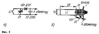
In the absence of a GSS, the IF bandpass filter can be adjusted by also connecting a small surrogate antenna to the first gate of the VT6 transistor through an isolation capacitor. Near the frequency of 2,3 MHz, I work with short-wave telegraph stations, and the L11C47 and L12C48 circuits are tuned to the maximum audibility. The setting of the L14C52 circuit is specified after, when receiving VHF stations with FM, according to the maximum volume to the quality of their reception. The operation of the local oscillator is checked by including a milliammeter in the power wire between the capacitor C45 and the zener diode VD7. Touching the LIOC40 circuit causes a breakdown of the oscillations and a slight increase in current. The local oscillator frequency is set by the capacitor C40 either by applying a signal with a frequency of 144 ... 146 MHz from the GSS to the input of the receiver, or by listening to the signal of your own transmitter (or other amateur radio stations). Somewhat higher in frequency, in the range of 146 ... 148 MHz, it is sometimes possible to listen to the work of service FM radio stations. The L8C32 and L9C36 circuits are adjusted to the maximum receive volume. The tuning of the L9C36 circuit somewhat affects the frequency of the local oscillator, and it has to be corrected by the resistor R27. Connecting an external two-meter whip antenna to the input of a properly tuned receiver causes a noticeable increase and change in the nature of noise in telephones. The transmitter is adjusted cascading, supplying voltage only to the tunable and previous cascades. A milliammeter must be connected to the power circuit. The simplest resonant wavemeter made on the basis of KPI with an air dielectric with a maximum capacitance of 75 ... 150 pF will provide invaluable assistance in setting up the transmitter. The wavemeter coil is a rectangular frame 50x15 mm in size, bent from a thick copper wire. The scheme of the wavemeter and the sketch of its design are shown in Fig. 5, respectively. 40, a and b. The wavemeter covers the range from about 160 to XNUMX MHz, which is quite enough for tuning. The scale of the wavemeter is calibrated according to the GSS signals. The indicator can be a conventional avometer, turned on to the minimum voltage measurement limit.
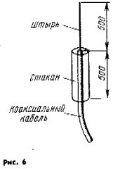
By turning on the master oscillator, they make sure that there is generation by changing the current in the power circuit when the quartz resonator is turned off or when the base of the transistor is closed to a common wire by a capacitor of considerable capacity. The L2C14 circuit is adjusted to the maximum current of the transistor VT2. Similarly, by connecting the power of the transistor VT3, adjust the circuit L3C17C18C19. The frequency (72 MHz) is controlled by a wavemeter. Before setting up the output stage, it should be loaded with the equivalent of an antenna - an incandescent lamp for a voltage of 13,5 V and a current of 0,18 A, the resistance of which in a heated state is close to 75 0m. The circuits L4C20 and L5C22C23 are tuned to a frequency of 144 MHz (controlled by a wavemeter) according to the maximum current of the transistor VT4 (up to 300 mA). An excessively high current indicates the need to reduce the excitation with the capacitor C 12, and then adjust the circuit with the trimmer of the coil L2 to the maximum current of the output stage. The output circuit is adjusted with capacitors C26 and C27, varying the ratio of their capacitances in such a way as to achieve the maximum brightness of the incandescent lamp - the load equivalent. The microphone amplifier does not require adjustment. It is only useful to check, by removing the frequency response of the amplifier, the cutoff frequency of the low-pass filter. The required modulation index is set by the resistor R2 when listening to the transmitter signal by other radio stations, by your own receiver, to which you only need to apply the supply voltage bypassing the "Receive" - "Transmit" switch, or using a spectrum analyzer. The modulation should be clean and deep, and the bandwidth of the emitted frequencies should not exceed 25..30 kHz at a level of -30 dB. The simplest radio station antenna can be a pin 0,25 m long, a quarter-wave "glass", which prevents current from flowing onto the cable sheath, and supplements the length of the antenna up to 0,5 m. The sketch of the antenna is shown in fig. 6.
The diameter of the pin and "glass" are not critical, the author used a piece of duralumin rod with a diameter of 6 mm and a piece of tube from a vacuum cleaner. Fastening to the insulating mast can be any; the metal mast should go inside the "glass" and have contact with it only near the point of connection of the cable braid. The latter may pass inside the mast tube. The radio station can work with other antennas, including directional ones. Author: V. Polyakov (RA3AAE) Moscow; Publication: N. Bolshakov, rf.atnn.ru
A New Way to Control and Manipulate Optical Signals
05.05.2024 Primium Seneca keyboard
05.05.2024 The world's tallest astronomical observatory opened
04.05.2024
▪ The origin of the hollow in the tree ▪ Asetek 645LT Compact PC Liquid Cooling System ▪ Solar panels LG NeON R and NeON R Prime
▪ section of the site Signal limiters, compressors. Article selection ▪ article Possible emergencies of a social nature on the territory of Russia. Basics of safe life ▪ article What characterizes the stellar magnitude? Detailed answer ▪ Swiss article. Standard instruction on labor protection
Home page | Library | Articles | Website map | Site Reviews www.diagram.com.ua |


 Arabic
 Bengali
 Chinese
 English
 French
 German
 Hebrew
 Hindi
Hindi Italian
 Japanese
 Korean
 Malay
Malay Polish
 Portuguese
 Spanish
 Turkish
 Ukrainian
 Vietnamese


 Leave your comment on this article: