|
|
ENCYCLOPEDIA OF RADIO ELECTRONICS AND ELECTRICAL ENGINEERING Radio station with amplitude modulation. Encyclopedia of radio electronics and electrical engineering
Encyclopedia of radio electronics and electrical engineering / Civil radio communications I propose a scheme for a radio station with amplitude modulation. Many nodes are taken from well-known designs, some have been modified and modified by their own. Particular attention during the development was paid to the simplicity of design, repeatability, the absence of a scarce element base, and ease of configuration. Schematic diagram radio station is given on fig.1a и fig.1b. Button SA2 serves as a mode switch "reception-transmission". When it is pressed, power is supplied to the transmitter, and an antenna is connected to its output. The microphone amplifier is designed as in [1] The use of an electret microphone and an amplifier-compressor with frequency response correction made it possible to increase speech intelligibility. When you press the SA1 "Call" button, the cascade on the op-amp DA1 generates a tone signal with a frequency determined by the circuit C6, R7 The amplified signal from the microphone amplifier is fed to the modulation depth control R13. Next, the signal is fed to the second stage of amplification and correction on the transistor VT1. The role of the modulator is performed by the cascade on VT2. The master oscillator of the transmitter is made on the transistor VT3, the frequency is stabilized by quartz ZQ1. A signal with a frequency of 27,41 MHz through the capacitor C17 enters the base of the transistor VT4. the emitter circuit of which includes a modulator on VT2. The modulated and amplified signal through the circuit C20, L14 is fed to the final amplifier on the transistor VT5. From the output of the power amplifier through the capacitor C22, the output P-circuit and the switch SA2.2, the signal with the operating frequency enters the antenna WA1. The receiving part of the radio station is made on the K174XA2 (DA2) chip. The signal from the antenna WA1 through the button SA2 2 is fed to the input amplifier on the transistor VT7, the load of which is the circuit L9, C29. From the communication coil L10, the signal is fed to pins 1,2 of the DA2 chip. An external local oscillator stabilized by ZQ2 quartz with a frequency of 26,945 MHz is assembled on a VT6 transistor. The local oscillator signal is fed to pin 4 of DA2. An intermediate frequency signal (465 kHz) from output 7 of the DA2 chip is fed to the detector. The detected signal, amplified by the cascade of the transistor VT8, through the high-pass filter C42, L14, C43 is fed to the volume control R35. Further, through the circuit R36, C45, the signal is fed to the ULF on a DA3 chip of the K174UN4A type. From pin 8 of the DA3 chip, the signal is fed to the dynamic head BA1 with a winding resistance of 8 ohms. On transistors VT9 and VT10, a battery discharge indicator is made. When the supply voltage drops to 6,5 V, the VD6 LED lights up. The indicator threshold is regulated by resistor R43. Design In the radio station, you can use resistors of the BC and MLT-0,125 W types. Trimmer resistors are of the SPZ-38a type. Electrolytic capacitors - K50-35 or imported for an operating voltage of at least 16 V, the rest of the capacitors - KM, KD or imported disk. The DA1 chip can be replaced with KR140UD1208 while maintaining the pin numbering, but the resistor R10 must be connected to a common wire. Transistors KT920A can be replaced by KT904A...B, KT610A...B, but this will reduce the output power of the transmitter. Diodes VD2...VD4 - any of the series KD521, KD522. Buttons SA1, SA2 - type KM-3, MP-1. Dynamic head 0,5 GDSH-1 can be replaced by 0,25 GDSH-2 or 0.1GD-17 (50 Ohm). Microphone MKE-3 - from portable tape recorders. The winding data of the inductors are shown in the table. Frames L11, L12, L13 are standard (IF circuits of transistor receivers).
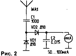
The ZQ1 and ZQ2 quartz resonators can also be used with other frequencies, such as 27,12 MHz and 26.655 MHz. The VT4 transistor is equipped with a radiator in the form of a ton plate, slightly larger than the transistor housing. For the transistor VT5, a cylindrical radiator made of duralumin with a diameter of 16 mm and a height of 17 mm was used. The radio station is made on a printed circuit board made of one-sided foil fiberglass with a thickness of 1,2 ... 1,5 mm. The board has cutouts for the speaker head, microphone, volume control, CP-50 connector and buttons. The battery discharge indicator is made on a separate board. The radio station is powered by seven D-0,55 batteries. The power supply compartment is separated from the main board by a partition. The radio station uses two types of helical antennas. Their frames are made of polyethylene from television cables of the RK brand. The diameter of the first blank is 9 mm, the second one is 7 mm. First, the top nut is unscrewed from the SR-50-74FV connector. The hole inside must be drilled and threaded M9x1,25, and on the workpiece for the first case, threaded to a length of 10 mm. For the second antenna - thread M7x0,75 mm. Having previously stretched the central core of the cable and stepped back from the edge of the thread 15 mm, a hole is made in the workpiece at an angle to pass the end of the winding wire through the center. This wire connects to the center pin of the CP-50 connector. After assembling the connector, start winding the antenna. For the first antenna (9 mm in diameter), first 77 turns of PEV-2 wire with a diameter of 0,4 mm are wound round to round, and then another 150 turns are evenly placed along the length of 29 mm. The end of the winding is fixed by fusing the wire into polyethylene. The antenna is described in detail in [2]. For the second antenna, the winding wire is also prepared before winding. They are wound tightly, coil to coil, wire - PEV-2 with a diameter of 0,5 mm for a length of 160 mm, and then 6 turns are unwound. The antenna was described in [3]. The design data of the antennas are valid for a frequency of 27,14 MHz. At other frequencies, for the first antenna it is necessary to wind 80 + 29 turns, for the second - close to a length of 160 mm. The end of the winding is temporarily fixed with tape. The antenna is connected to the radio station, and in the "transmission" mode, unwinding 1 turn each (in the first case from 80 turns), tune to the maximum radiation. The control is carried out according to the field strength indicator, the scheme of which is shown in Fig.2. All parts of the indicator are assembled on the M24 head terminals. A piece of copper wire 15 ... 25 mm long serves as an antenna.
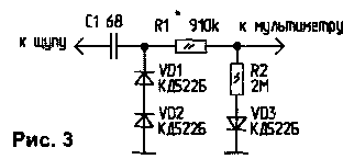
After the final adjustment of the antennas, they must be placed in a protective shell. Along the length of the antennas plus 2 ... 3 cm, a piece of vinyl chloride tube with a diameter of 8 ... 10 mm is cut off. Place it in a jar and fill it with acetone or solvent for 5-10 minutes. Time is specified experimentally. The tube must be completely immersed in the liquid. Then they take it out, shake off the acetone and put it on the antenna. The tube becomes elastic, and it can also be pulled over the CP-50 connector. In the recess where the rotating part of the connector is located, the tube is fixed with 3 ... 5 turns of a strong thread. Then the second end is pulled out so that the tube tightly fits the antenna winding. With the same thread, the tube is pulled together at the end of the antenna. For the elongated free end of the vinyl chloride tube, the antenna is suspended for 2-3 days, and only then the threads are removed, and the ends of the protective sheath are carefully cut off. You can put a felt-tip pen cap on the top of the antenna. Antennas are tuned after the transmitters are assembled and configured. To measure RF voltages, if there is no RF voltmeter, you can use a digital multimeter with an input resistance of at least 1 MΩ and an external high-frequency detector. The scheme of the RF detector is shown in Fig.3.
The setup starts with a microphone amplifier and ULF. The output of resistor R13 is connected to capacitor C44 and power is supplied to both amplifiers. Speaking into the microphone, check their work. If desired, capacitor C6 can select the frequency of the tone call. The generator is tuned by rotating the coil trimmer L1. An RF voltmeter (multimeter) is connected to the base of the VT4 transistor. Having achieved maximum readings, by adjusting L1, stable generation is achieved. Connect the equivalent of an antenna with a resistance of 50 ohms (2 MLT-1 resistors of 100 ohms in parallel) to the CP-50 antenna connector, and a voltmeter to the VT5 base. Power is supplied by the SA2 button, and by rotating the L3 core, compressing or stretching the turns of the L4 coil, the maximum readings of the device are achieved. Then the RF voltmeter is connected to the dummy antenna. The output P-circuit is adjusted by stretching or compressing the turns of the coils L6, L7. The setting of the receiving part has no special features. It is desirable to power the radio station when setting up in the "transmission" mode from a stabilized power source with a voltage of 9 V, because. in this case, a current of about 400 mA is consumed (when receiving at an average volume - 25 ... 30 mA). If the radio station is installed permanently, the power supply can be made according to the scheme described in [4], by lowering the supply voltage to 9 V. At a supply voltage of 12 V, the value of the resistor R34 should be increased by 100 ... 150 Ohm. When testing a radio station with spiral antennas in crowded areas, the communication range reached 3 ... 5 km. If you use the antenna described in [5], the range increases to 8...10 km. Charger for batteries D-0,55, NGKTs-0,5 can be made according to the scheme shown in Fig. 4. For batteries D-0,25, the capacitance of the capacitor C1 must be reduced to 0,47 microfarads.
Literature
Author: M.Trotsenko, Belgorod; Publication: N. Bolshakov, rf.atnn.ru
A New Way to Control and Manipulate Optical Signals
05.05.2024 Primium Seneca keyboard
05.05.2024 The world's tallest astronomical observatory opened
04.05.2024
▪ NZXT C Series Bronze Power Supplies ▪ While playing, the brains of parents and babies are synchronized ▪ Space garbage truck projects
▪ section of the site Amateur radio calculations. Article selection ▪ article Organizational Behavior. Crib ▪ article What explains the cute behavior of slow lorises when tickled? Detailed answer ▪ article Sea horseradish. Legends, cultivation, methods of application ▪ article Parallel phone blocking. Encyclopedia of radio electronics and electrical engineering
Home page | Library | Articles | Website map | Site Reviews www.diagram.com.ua |


 Arabic
 Bengali
 Chinese
 English
 French
 German
 Hebrew
 Hindi
Hindi Italian
 Japanese
 Korean
 Malay
Malay Polish
 Portuguese
 Spanish
 Turkish
 Ukrainian
 Vietnamese


 Leave your comment on this article: