|
|


 Arabic
 Bengali
 Chinese
 English
 French
 German
 Hebrew
 Hindi
Hindi Italian
 Japanese
 Korean
 Malay
Malay Polish
 Portuguese
 Spanish
 Turkish
 Ukrainian
 Vietnamese
|
ENCYCLOPEDIA OF RADIO ELECTRONICS AND ELECTRICAL ENGINEERING Protection of speaker systems from overloads. Encyclopedia of radio electronics and electrical engineering
Encyclopedia of radio electronics and electrical engineering / Speakers 2. Protection systems The second part of the article will talk about protecting speakers from overloads and other consequences of incorrect ULF operation. In most cases, the speakers used are more expensive than the amplifiers they are loaded on. Next, options for implementing their protection will be considered. 2.1 Overload protection 2.1.1. Diagram with direct connection This circuit uses a signal taken directly from the ULF output and breaks the circuit if the maximum permissible signal level is exceeded. The scheme is shown in fig. one.
In normal mode, the relay is on - this makes it possible to avoid popping when the ULF is turned on. The scheme is very simple and not demanding to set up. Only R3 is of fundamental importance, for the rest of the elements there will be only recommendations. So let's calculate R3. To do this, we need the load capacity of Schmitt triggers. For such inclusion, it is recommended to select triggers of the TTL or TTLSH family.
R - resistance R3
Resistor R4 is designed to remove parasitic potentials from the VT2 base and can be varied within 10 ... 30 kOhm. the supply voltage of the device must exceed the relay actuation voltage by approximately 1V. VT2 is selected according to two criteria: Uke ≥ E, Ik ≥ Ir. VT1 - any low-power transistor with Uke ≥ E. R1 and R2 are selected depending on the ULF output voltage. U - ULF output voltage
Electrolytic capacitors C1, C2 set some inertia to the input triggers. This avoids false short-term responses at peaks. Any diodes can be used, with an operating frequency of at least 100 kHz. Slightly higher requirements for VD5. Ietc.≥ 500 mA Uarr≥E. the operating frequency is not important, because this circuit operates with direct current. Setting system is reduced to setting the threshold, which is performed in the following order. 1. Set the engines R1 and R2 to the lower (according to the diagram) position.
Using the relay, you can disconnect the speakers from the amplifier or turn off the power to the amplifier itself. One of the possible options is shown in Fig. 2
In working condition, the triac is open. When the relay is actuated, the simistor UE circuit breaks and the amplifier power is turned off. R1 is calculated as follows:
where: R - resistance R1
If the ULF is powered by a separate transformer, you can disconnect it from the network. A variant of the implementation of such a block is shown in Fig. 3 The trinistor KU202N is used in the circuit.
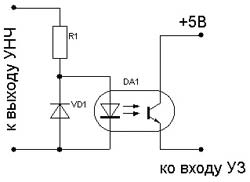
2.1.2 Optocoupler circuit Saves the output of the amplifier from any influences from the US. The design itself is supplemented only by optocouplers at the input. The simplest version of the addition is shown in Fig. four
The diode part of the optocoupler is connected to the ULF output through the resistor R1. At power peaks, the diode should reach its maximum "brightness". As can be seen from the diagram, a common bus contact is not needed for operation, therefore, such a circuit can be used to work in ULF bridges. R1 is calculated according to Ohm's law for the circuit section:
where R - resistance R1
The microcircuit supply voltage is applied to the collector of the transistor. 2.2. Thermal protection It is used to protect the output stage from overheating. The sensor is a thermistor. When designing such devices, it should be borne in mind that the dependence of resistance on temperature can be both direct and inverse. This determines the location of the thermistor in the input divider. A possible version of the scheme is shown in Fig. 5. The thermistor is pressed with a clamp to the OK radiator or is attracted with screws (depending on the TP version). In the proposed variant, TR has an inverse characteristic.
The ultrasound is based on a comparator that compares the voltage across the thermistor with a certain reference (reference) created by the divider R3R4. Thus, using R4, you can set the response threshold (temperature) of the device. You can get rid of the bounce of the relay, in the transition state, by selecting R5. the device operates in the range of 8-36V, depending on the type of relay used. Authors: Ulitin Pavel A., Soundoverlord, Chistopol, Tatarstan, Soundoverlord [bug]bk.ru. ICQ: 2-058-996; Publication: cxem.net
Artificial leather for touch emulation
15.04.2024 Petgugu Global cat litter
15.04.2024 The attractiveness of caring men
14.04.2024
▪ The most dangerous virus on earth ▪ Mushrooms found to extract gold from the soil ▪ Vortex thermosyphon cooler - a new source of energy
▪ section of the site Lecture notes, cheat sheets. Selection of articles ▪ article History of Pedagogy and Education. Crib ▪ article When did you first use combs? Detailed answer ▪ article by Shumannia Karelin. Legends, cultivation, methods of application ▪ article Phenomenal memory. Focus secret
Home page | Library | Articles | Website map | Site Reviews
www.diagram.com.ua |


 where:
 where:
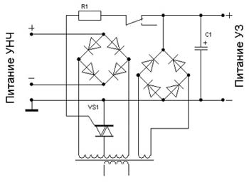
 ,
,
 ,
,
 Leave your comment on this article: