|
|


 Arabic
 Bengali
 Chinese
 English
 French
 German
 Hebrew
 Hindi
Hindi Italian
 Japanese
 Korean
 Malay
Malay Polish
 Portuguese
 Spanish
 Turkish
 Ukrainian
 Vietnamese
|
ENCYCLOPEDIA OF RADIO ELECTRONICS AND ELECTRICAL ENGINEERING Economical, sensitive, stereo radio receiver. Encyclopedia of radio electronics and electrical engineering
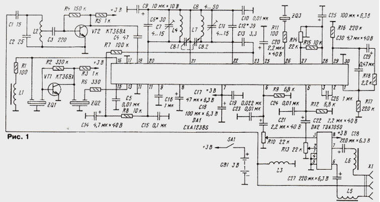
Encyclopedia of radio electronics and electrical engineering / radio reception If you or your friends bought a Chinese-made receiver and it soon failed, then do not rush to throw it away. Using a quite nice case, a KPI block and the scheme proposed here, you can assemble a stereo receiver in a day or two, which is not inferior in sensitivity and sound quality to branded ones, and surpasses most of them in efficiency. When repairing a car radio from a little-known company, the author came across a CXA1238S chip, which, as it turned out, works fine even with a supply voltage of 2 V and consumes a small current - about 12 mA. In the author's version of the receiver, it is included not quite standardly. To increase the sensitivity, an additional cascade of IF was introduced. In addition, the URC was introduced for the same purpose. The result was a fairly simple, sensitive receiver with a high degree of repeatability, low cost, and non-critical to the ratings of parts. Since it uses the elements of the finished product to the maximum, the operating range remains the same - 88 ... 108 MHz. The receiver remains fully operational when the supply voltage drops to 1,9 V, consumes a current of about 16 mA (for branded ones - 30 ... 45 mA). When using batteries type "GP" with a capacity of 1300 mAh, the power supply is enough for almost a month when working 3 hours a day. The design does not contain labor-intensive manufacturing of IF filter coils with a frequency of 10,7 MHz and is assembled on two inexpensive microcircuits - СХА1238S from Sony and TDA7050 from Philips. It is not difficult to buy them in cities. The schematic diagram is shown in fig. 1. Induced in the antenna, the role of which is played by the common wire of stereo telephones, the signals of radio stations in the range of 88 ... 108 MHz are fed to the input oscillatory circuit L2C2. It is tuned to the middle of the range. The preliminary URF is assembled on a low-noise transistor VT2 according to an aperiodic circuit with a common emitter. The amplified radio signal is fed to pin 18 of the DA1 chip (URCH input). The load of this URCh is a tunable oscillatory circuit L4C6C7C8.1. The signal from it is fed to the mixer as part of the microcircuit. It also receives the local oscillator voltage, the circuit of which is L7C11C12C13C8.2.
The 10,7 MHz IF signal from pin 16 of the microcircuit is allocated to the mixer load R1L1, filtered by the piezoceramic filter ZQ1, amplified by the cascade on VT1, additionally filtered by the same filter ZQ2 and fed to input 13 of the microcircuit limiter amplifier. To demodulate frequency-modulated oscillations, the phase detector of the DA1 microcircuit is used. Its phase-shifting circuit ZQ3R11 is connected to pin 26 DA1. The ZQ3 filter has a phase characteristic similar to that of an oscillatory circuit with a quality factor of about 20, its use avoids winding a bulky inductor. The chip's stereo decoder works with time division, using a PLL to synchronize with the pilot tone. Resistors R14, R15 set the frequency of the built-in VCO. Elements C29C30R18 - proportionally integrating PLL filter, R16 and R17 set the DC mode. The signals of the left and right stereo channels are generated at pins 6 and 5 of DA1, respectively. The R9C23 and R12C24 chains are used to compensate for the pre-emphasis of the audio signal input on the transmitting side to improve the signal-to-noise ratio. The TDA7050 chip was chosen as an audio frequency amplifier (UHF) - it has a small quiescent current in the no-signal mode (about 3 mA) and it requires a small number of connected elements. Most of the stereo telephones that come with radios greatly attenuate low audio frequencies when playing signals. To compensate for this shortcoming, many companies began to introduce Bass boost systems into their products. For those who want to use a similar improvement to improve the sound quality in fig. 2 shows a diagram of one of the possible options.
Chokes L3, L5, L6 isolate the RF signals induced on the headphone wire from the common wire. Elements R8, C14, C15 filter the AFC signal generated at pin 10 DA1. It enters the varicap (pin 23) built into the microcircuit - its capacitance is added to the capacitance of the local oscillator circuit in series with the capacitance of capacitor C13. The author could not establish the capacity of the KPI used due to the lack of an appropriate meter, but all the imported copies at his disposal, taken from Chinese technology, most likely had the same capacity of the VHF sections, since they successfully worked with coils, the winding data of which are given below. It will not be difficult for a radio amateur with even a little experience to adjust the manufacture of coils of oscillatory circuits for his existing KPI. In the receiver, you can use resistors of any type with a tolerance of at least + 20%. Small-sized oxide capacitors of the K50-40 type are better suited, but it is quite acceptable, if the dimensions of the structure allow, to use capacitors of the K50-16, K50-35 or imported types. The remaining capacitors are KM-3, KM-4 or other small ones. I would like to emphasize that the proposed circuitry version of the receiver is not critical either to the types or to the ratings of the elements included in it. Piezoceramic filters are any broadband, small-sized, used in all receivers with the VHF range. The ZQ3 filter does not seem to have domestic analogues. It can be replaced by the circuit shown in Fig.3.
Dual resistor (R10, R13) with an inverse logarithmic resistance change characteristic (group B), for example C2-6v. Group A resistors can also be used, in which case it is necessary to connect the outputs of their engines to a common power bus through resistors with a resistance equal to 1/8 of the resistance of the variable resistor. Transistor VT1 - KT368A, KT368B, KT3102 with letter indices from A to E; VT2 - KT368A, KT368B, KT339 or KT399 with any letter indices. The CXA1238S chip has no analogues among microcircuits manufactured by other companies, but it can be purchased in the markets and in stores selling radio elements for repair. The TDA7050 audio frequency amplifier chip will be completely replaced by any with a similar functional purpose. It is only important that it has a low-voltage power supply and a low quiescent current. In terms of parameters, the KR174UN23 microcircuit is close to it. The inductance of the inductor L1 can be in the range from 22 to 220 μH, and the inductors L5 and L6 - from 2,2 to 22 μH. Coils L2 - L4 and L7 are frameless with an inner diameter of 3 mm, wound with PEL-0,33 wire. Coil L2 has 8 turns with a tap from the middle; L3, L4 and L7 - respectively 10, 4 and 3rd turn. The exact number of turns depends on the length and location of the tracks leading to the coils on the printed circuit board, on a specific KPI instance, and is specified during configuration. If the installation of the receiver is carried out without errors and the elements correspond to the recommended ones, then when the power source is turned on, characteristic noise should appear in the stereo phones. It is necessary to temporarily disconnect the capacitor C4, replace the coil L4 of the IF filter with any choke, and connect a piece of wire about 18 m long to pin 1 of the DA0,5 chip. If this fails, try changing the number of turns of the heterodyne coil. A constantly working AFC system will let you know that you have tuned in to the mirror channel - the setting will be "floating", fuzzy. In this case, stretch the turns of the L7 coil or reduce the number of turns until the same station appears with a clear tuning. If the receiving frequency range turns out to be too wide (operating radio stations are concentrated in the middle part of the scale), you should increase the capacitance C12 (coarsely) or C11 (smoothly), while reducing the inductance of the L7 coil to maintain the setting. Accordingly, in the case of too narrow a range that does not allow reception of all working radio stations, take measures of the opposite nature. After that, you need to connect a voltmeter (oscilloscope) to pin 25 of the DA1 chip. Soldering the L4 coil and shifting or expanding its turns (or changing their number), you should achieve maximum voltmeter readings (in this case, the receiver must be tuned to some station, and the position of the surrogate antenna must not be changed). In conclusion, the final conjugation of the contours is performed. Restore the inclusion of capacitor C4 and trimming resistor R14 to achieve stable stereo reception. The L2C2 circuit can also be adjusted to the maximum reading of the voltmeter, but due to its low quality factor, it is hardly worth doing. Those who wish can add a "stereo" indicator, for which an LED is suitable, the anode of which is connected to the power plus, and the cathode through a 560 Ohm resistor to pin 4 of the DA1 microcircuit. I also want to note that the CXA1238S chip also allows you to implement a receiver of amplitude-modulated signals (long, medium and short waves) with an intermediate frequency value of 455 or 465 kHz. Author: D. Ryvkin, Vsevolzhsk, Leningrad Region
Artificial leather for touch emulation
15.04.2024 Petgugu Global cat litter
15.04.2024 The attractiveness of caring men
14.04.2024
▪ The most powerful supercomputer built
▪ section of the website Residual current devices. Selection of articles ▪ article by William Butler Yeats. Famous aphorisms ▪ article What part of capsicum is the hottest? Detailed answer ▪ article Operator of washing machines. Standard instruction on labor protection ▪ article Two magic wands. Focus secret
Home page | Library | Articles | Website map | Site Reviews
www.diagram.com.ua |


 Leave your comment on this article: