|
|


 Arabic
 Bengali
 Chinese
 English
 French
 German
 Hebrew
 Hindi
Hindi Italian
 Japanese
 Korean
 Malay
Malay Polish
 Portuguese
 Spanish
 Turkish
 Ukrainian
 Vietnamese
|
ENCYCLOPEDIA OF RADIO ELECTRONICS AND ELECTRICAL ENGINEERING Program selection block for the receiver. Encyclopedia of radio electronics and electrical engineering
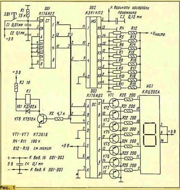
Encyclopedia of radio electronics and electrical engineering / radio reception Manufacturers of REA pay considerable attention to the issues of improving operational convenience. In their designs, radio amateurs also tend to think through the issues of automating various processes, in particular, adjustments and settings in the devices they create. One example of this is the proposed description of a one-button program selection box in a radio receiver. The block developed by the author is designed for use in broadcasting receivers with electronic tuning. It provides a choice of eight programs with just one button. This provides a certain convenience to owners of portable and car radios in comparison with designs that use a smooth or multi-button tuning system to a received radio station. It is advisable to apply this method in stationary tuners with an expansion of the choice to 16 programs. In contrast to previously published descriptions [1, 2], the proposed version of the device is made using only three microcircuits, it provides for the possibility of automatic band switching and is equipped with a digital indicator for visual identification of the selected program. Schematic diagram of the device is shown in Fig.1. When the power is turned on, the DD1 chip is set to the zero state (code 0000). This code sets the multiplexer (chip DD2) to a state in which its output (pin 3) receives the input voltage X0 (pin 13). The output voltage of the multiplexer is used to feed the varicap(s) of the receiver. The voltages at the inputs X0 - X7 are set by the corresponding tuned resistors R4-R11 and determine the reception of a particular radio station.
When the button SB1 is pressed briefly, the code at the output of the counter DD1 changes and, accordingly, the voltage at the output of the multiplexer. The code decoder, made on the DD3 chip, converts the counter output code into a position code to turn on the segments of the HG1 seven-segment LED matrix. When the power is turned on, the LED indicator lights up the number 0, and with each subsequent press of the SB1 button, the indicator readings increase by one. Each indication of the indicator corresponds to a well-defined received program (set by choosing one of the tuned resistors). When the counter reaches code 1000, the indicator flashes "0" again, and the receiver's tuning elements are energized from the X0 input of the multiplexer. The proposed version of the program selection block can work in dual-band receivers. At the same time, four pre-installed programs are selected in each of them. In this case, using the device will allow automatic band switching. This is done in a cascade on the transistor VT1. After code 0011 (the fourth installed program of one range), when code 0100 appears (the first program of another range), transistor VT1 opens and relay K1 is activated, which, with its contacts, acts on the receiver range switching elements. When code 1000 is reached, the transistor switches to the closed state and the first range is switched on again in the receiver. As an example, Fig. 2 shows a switching option for a dual-band VHF receiver [3].
If automatic range switching is not required, then the elements R2, R3, VT8, VD1 and K1 can be excluded from the circuit. The device is powered from the current source of the receiver itself (in stationary receivers, separate power supplies can also be used). An essential requirement is only the need to provide a well-stabilized Uset. But, as a rule, this is solved quite well in the receiver itself, therefore, for this purpose, it is also necessary to use the capabilities of the basic design of the receiver to the maximum extent. The design of the program selection device can be arbitrary, depending on the dimensions of the receiver where it will be used. It is equally possible to use mounting on a printed circuit board (the author did not make such a board) or hinged on mounting racks. The device can use resistors of the MLT or BC type with a dissipation power of 0,125 and 0,25 W. the use of large resistors is impractical. The diagram does not show the nominal values of the resistors R12 - R19. They must correspond to the settings of the receiver in which this device will be used. Adjusted resistors - type SPZ-36. KT361B transistors can be replaced with transistors of the same group with letter indices G.E.Zh.K or MP26B transistors. As an indicator, it is possible to use an LED matrix of the specified type, but with other letter indices, or another type with a common anode, for example AL305A (in the latter case with the selection of resistors R20 -R26). Relay K1 - types RES-9 (version 4.524.202), RES-22 (version 4.500.129) or other small-sized relay with an operating voltage of 9 ... 10V and a current of not more than 100 mA. When using a relay with a working current of less than 30 mA, as VT8, you can install a transistor of the KT315 series with any letter index. Adjustment of the device is reduced to the selection of resistors R20 - R26 according to the required brightness of the glow of the segments of the indicator matrix and the installation of tuned resistors R4 - R11 when choosing the voltages supplied to the receiver varicap when choosing the desired radio stations. It should be noted that the voltage on the engines of the resistors R4 - R11 does not exceed 9 V. Literature
Author: A.Vaganov, Novosibirsk
Artificial leather for touch emulation
15.04.2024 Petgugu Global cat litter
15.04.2024 The attractiveness of caring men
14.04.2024
▪ Increasing popularity of cell phones with cameras ▪ Protein from algae, sugar and light ▪ Global warming will provoke a record number of migrants ▪ Robots will build a giant telescope on the moon
▪ section of the site Life of remarkable physicists. Article selection ▪ article Types of means and methods of sending distress signals. Basics of safe life ▪ Article Actinidia Amur. Legends, cultivation, methods of application ▪ article TTL signal transmitter. Encyclopedia of radio electronics and electrical engineering ▪ article House from postcards. Focus Secret
Home page | Library | Articles | Website map | Site Reviews
www.diagram.com.ua |


 Leave your comment on this article: