|
|


 Arabic
 Bengali
 Chinese
 English
 French
 German
 Hebrew
 Hindi
Hindi Italian
 Japanese
 Korean
 Malay
Malay Polish
 Portuguese
 Spanish
 Turkish
 Ukrainian
 Vietnamese
|
ENCYCLOPEDIA OF RADIO ELECTRONICS AND ELECTRICAL ENGINEERING Circuitry of a detector radio receiver for 100 years. Encyclopedia of radio electronics and electrical engineering
Encyclopedia of radio electronics and electrical engineering / radio reception A detector radio receiver is classified as a radio device in which the received radio signals are not amplified, but only detected. The detection process is understood as the conversion of modulated high-frequency oscillations into the original low-frequency modulating signal. A device for performing detection is called a detector. Detectors, depending on the amplitude of electrical oscillations, are divided into two types: those operating under the influence of the maximum level of electrical oscillations (coherer, magnetic detector) and detecting all amplitudes of electrical oscillations (crystal, lamp and electrolytic detectors) [1]. The most widely used crystal and lamp detectors. Depending on the switching circuit of the electron tube, detection is distinguished: anode, grid and cathode. Detector radios may or may not have a power source, depending on what type of detector is used in their circuits. The power supply is necessary for the operation of the coherer, magnetic and electrolytic detectors. With regard to the tube detector, a radio receiver with such a detector is already classified as a tube device. An amplifier of any type (UHF or UHF) cannot be included in the detector radio circuit, otherwise, depending on the electronic components used in it, it will be called a tube or transistor receiver. The name "detector radio receiver" is usually associated with a receiver having a crystal detector [2]. Headphones in such a device work only due to the energy of radio waves received by the antenna from the air. The efficiency of receiving radio stations by a radio receiver depends on the type and quality of the antenna. For a detector receiver, it is best to use external antennas, L-shaped or T-shaped. The named antennas differ only in the place of attachment of the drop. It would seem that the antenna is longer and suspended higher, the more energy it can capture, and the headphones will sound louder. However, practice has shown that in this case there is a reasonable limit. The optimal length of the antenna is 40...50 m, and the height of its suspension is 10...15 m. The greatest distances at which reliable and regular reception of broadcasting stations is possible depends mainly on the power of the transmitting radio station, the receiving wavelength and the time of day, Table 1. The operation of a crystal detector before the advent of semiconductor technology largely depended on its design, the selection of materials for the contacting pairs, and the degree of contact compression. The contact pair is selected in a certain way and can be formed both by two crystals and by a crystal with a metal tip. In the designs of detector receivers, the contact pair crystal - metal tip is most widely used. Contact pairs, depending on their nature, have different ability of one-way current conduction, which can be characterized by a dependence of the form l=f(U), where I is current, U is voltage. Based on this dependence, when choosing detectors, preference should be given to those that pass current better in the forward direction and worse in the reverse direction. As a result of touching the sharp end of the spring on the surface of the crystal, a contact is formed. In such a contact, the electrical resistance when the current flows from the spring to the crystal is significantly different from the electrical resistance when the current flows from the crystal to the spring. In other words, in such a detector design, the current flows in only one direction. Many substances have the ability to pass current in one direction, but the natural minerals galen, pyrite, chalcopyrite, etc. are the best. Basic information about the crystals used for detectors is given in Table 2. As for the carborundum detector, it is necessary to use a galvanic battery to set the best operating point in it. The characteristics of some detector pairs are given in Table 3. Headphones are also chosen depending on the type of crystal used in the detector. In the detector receiver, electromagnetic headphones with a voice coil resistance of 1000 ohms or more, low-ohm headphones with a coil resistance of less than 300 ohms, as well as piezoelectric headphones can be used. The most common are high-impedance headphones. Low-resistance headphones are used in receivers with a low-resistance detector, such as carborundum steel, but such detectors are not widely used. In some cases, when the radio transmission is heard loud enough, it becomes possible to connect a subscriber loudspeaker instead of headphones and thereby expand the listening audience. You can amplify the sound of headphones in the absence of such a speaker by attaching a horn of a certain shape and size to the headphones. The horn can be made from any material, such as paper or cardboard, but it is better to use wood. Table 1
Table 2
Table 3
The main disadvantage of a crystal detector with a spring-loaded tip is the possibility of breaking the contact during operation. A slight mechanical (shaking) or electrical impact can disrupt the stability of the contact and thereby lead to the loss of the working detection point. In this case, the reception disappears altogether, and to resume it, it is necessary to manually rearrange the tip of the spring on the crystal surface, that is, to set a new detector point. The design of the crystal type contact - the tip of the metal spring was the Achilles' heel of the crystal detector. A large number of detector designs were proposed, in which, according to the authors of the inventions, the goals of reliable and stable contact were achieved, Fig.1.
Due to the rapid development of the semiconductor industry in the mid-50s, variable contact detectors were replaced by germanium-based semiconductor point diodes. In the new detectors, instability in operation was eliminated due to the strong mechanical contact of the tip of the spring with the crystal. These were the so-called point diodes with a pn-type junction. The pn junction was fabricated using the electrical forming method. The method consists in passing powerful short-term current pulses through a point contact. As a result, the contact point is heated and the tip of the needle is fused with the semiconductor. Under the contact, a small hemispherical pn junction is formed, resembling a dot. The point diodes obtained in this way have stable electrical parameters and high mechanical strength. Detector radio in its development The detector receiver with a crystal detector and headphones was for a long time the most common radio receiver due to its simplicity and low cost. Detector reception is a whole era in the history of the development of radio engineering. The main advantage of this receiver is that it does not require an electric current source. The popularity of the detector receiver could be the envy of modern receivers. For example, at the end of the 20s there was a jazz party in Moscow, music lovers made detector receivers and listened to live broadcasts of concerts from London, and then wrote down notes from memory. After some time, music lovers met and compared the records. Radio amateurs assembled detector receivers in the form of pocket structures, using cigarette cases, matchboxes and the like for this purpose, Fig.2. In our country, among radio amateurs, a detector receiver without a variable capacitor, designed by S.I. Shaposhnikov, an employee of the Nizhny Novgorod radio laboratory, was widely used.
To tune into the radio station, a variometer was used, consisting of two cylindrical coils wound with a bell wire with a diameter of 1,5 mm. A description of the design of this detector receiver was placed in the Soviet magazine "Radio Amateur" No. 7 for 1924. The detector receiver circuit did not have any features, the main thing was the simplicity of manufacturing the design itself. In the 1926th century, many circuits and designs of detector radios were developed. For many of these schemes and designs, the authors received patents, which indicated the novelty of the developments. Some of these circuit solutions are still in use today, and now we don't even suspect that they are patented. Let's dwell on some of the most interesting patents received in different years. In 3, V.E. Prikhodko proposed a detector receiver scheme called "Device for receiving without tuning and grounding", Fig. 3 [4]. The following year, the same inventor patented an improved version of the receiver based on a previously developed circuit. In this scheme, one of the diodes was replaced by an oscillatory circuit, Fig. 4 [3]. To increase the power of receiving radio stations in the receiver without tuning and grounding [5], two capacitors and grounding were added to its circuit, Fig. 5 [1929]. In 6, F.A. Vinogradov developed and patented a detector receiver circuit, in which a single-period detector circuit with voltage multiplication was used, Fig. 6 [7]. The purpose of this invention was to obtain loud-speaking reception of the radio station on a loudspeaker, which is included in the receiver jacks instead of telephones. According to the above schemes, the author of this article assembled detector radio receivers from modern parts, and on a small outdoor antenna about XNUMX m long, he managed to receive the signals of many radio stations broadcasting in the north-west of Russia. However, a more interesting circuit solution for increasing the reception volume was a circuit with two low-frequency transformers and a galvanic battery, Fig. 7 [7]. In this circuit, the headphones are connected to the primary or secondary winding of one of the low-frequency transformers. The last patents for detector radio circuits were issued in the early 50s. A group of authors proposed a tubeless radio receiver that allows you to listen to radio broadcasts on a loudspeaker, Fig. 8 [8]. In essence, it was a detector receiver with a so-called piezoelectric amplifier powered by a galvanic battery. According to the authors, the radio should have worked as follows. Under the action of sound frequencies coming from the output of the detector radio receiver (1) not the piezoelectric element (2), mechanical vibrations of the piezoelectric element occur. These oscillations correspond to the frequency and amplitude of the input signals. The impact of mechanical oscillations of the piezoelectric element changes the density of the carbon balls in the push-pull microphone (3), which in turn leads to a change in the current flowing in the primary circuit of the transformer (5). By induction, an alternating voltage arises in the secondary winding of the transformer, which causes the piezoelectric element of the loudspeaker to oscillate. Naturally, and this is noted by the authors, the gain and power output by such an amplifier depend on the efficiency of the piezoelectric element, the voltage and power of the microphone battery with the appropriate characteristics of the microphones used. It is not known whether a working receiver design was created according to this scheme, but a patent for a beautiful idea was received.
Detector radios were produced by the domestic industry until the middle of the 1th century. In order for such a radio receiver to work, it was only necessary to connect headphones, an antenna, ground and a crystal detector to its corresponding jacks. At first, by rotating the tuning knob of the variable capacitor or moving the alsifer core inside the loop coil, a signal was searched for a radio station. After that, the listener tried to increase the transmission volume and moved the wire along the surface of the detector crystal, that is, he was looking for a sensitive receiving point. In industrial receivers, preference has been given to the usual circuit, consisting of a single oscillatory circuit, a detector and high-impedance telephones. The most famous detector radio receivers produced by the domestic industry were Komsomolets, Volna, ZIM-9, etc. The diagram of the Komsomolets receiver is shown in Fig. 180a. The receiver had dimensions of 90x49x350 mm and a weight of 9 g, Fig. 1949b. Smooth tuning at the radio station was carried out by moving the alsifer core inside the coils using a small crank mechanism. In 52, the cost of the detector receiver itself was 56 ... 18 rubles, electromagnetic headphones 40 rubles. 28 kopecks, and piezoelectric - 5 rubles. A cheap tube battery receiver "Rodina" cost almost six times more than a detector receiver. At the same time, the listener's fee for the detector receiver was 7 rubles. per year, that is, 1050 times less than for a tube radio. For comparison, during this period of time, the salary in our country for a novice researcher was 800 rubles, and for a young engineer at a plant - XNUMX rubles.
With a careful attitude, the detector radio receiver could serve for a very long time without the need to replace any radio components, which was then of no small importance. And yet, in the post-war period, not every citizen of our country could purchase a fully equipped detector radio. In order to reduce the cost of the detector receiver, the scientists of LETI (Leningrad Electrotechnical Institute) Bogoroditsky N.P. and Evteev F. developed a cheap and simple in technological production design of a simple detector receiver, Fig. 10a [9]. In essence, the receiving device was a detector radio receiver with a contour inductor printed on a porcelain disk 120 mm in diameter and 8 mm thick, Fig. 10b. Field connections and coil turns were made with a conductive paste containing dispersed silver. The paste was applied into spiral grooves on both sides of the disk. The disc was fired in a muffle furnace at a temperature of 800°C. The strength of the connection of the circuit elements with the surface of the porcelain disk was very high. After that, two rotating disks of ceramic capacitors (of the KPK-2 type) and brass tubes-jacks for connecting headphones, a detector, an antenna, and ground were installed on the front surface of the disk. The radio receiver did not have a case, and in case of contamination, it could simply be washed in warm water with soap, without fear of damaging the radio components. This receiver of unusual design was capable of receiving, with a sufficient loudness, radio stations in the 25 ...
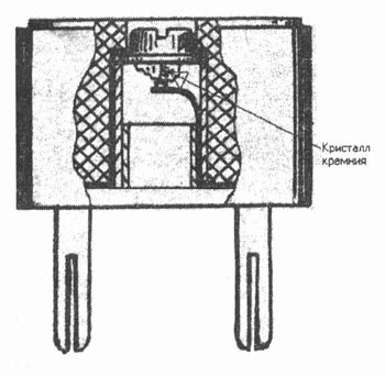
Domestic industrial detector radios were designed to receive radio stations in the long and medium wave bands. To operate these receivers, a standard-sized outdoor antenna was required, as well as grounding in the form of a metal sheet measuring at least 60x60 cm.2, buried in the ground to a depth of 1 ... 1,5 m. In domestic detector receivers, an industrial sample of the detector was mainly used, made in a plastic case resembling a plug, Fig.11. One pin of such a plug was attached to a cup with a crystal using a flat metal plate. The cup had a slot for a screwdriver and was structurally located in the middle of the case with the crystal down. This allowed, using a screwdriver, to rotate the cup with the crystal, which was touched by the end of a thin spring connected to another pin of the plug. During rotation, a search was made for a sensitive detection point. With the development of the production of point germanium diodes by the industry, detectors in the form of a plug continued to be produced, but a germanium point diode was already installed inside it, the leads of which were soldered to the pins of the plug. Detector radio in the XXI century Until now, the detector radio is still especially valuable for hard-to-reach areas, in the country house and garden plot - where there are no sources of electricity. For good operation of the detector radio, the main thing is to install a high-quality antenna and grounding. Under favorable conditions, loud-speaking reception of radio stations is possible on a subscriber loudspeaker, switched on instead of headphones, and reception of short-wave radio stations. Currently, there are significantly more radio stations on the air than in the era of its popularity, so a modern detector radio receiver must, first of all, have high selectivity. Achieving the required selectivity is possible only with the complexity of the circuit and design of the radio receiver. The main circuit solutions for detector radio receivers with high selectivity were developed back in the 20s of the last century. They still have not lost their significance and are of interest to developers of such structures. Descriptions of the so-called "new" designs of detector radios that periodically appear in amateur radio magazines are basically "well-forgotten old" circuit solutions of the first half of the XNUMXth century.
Input circuits are the main selective elements of detector receivers, which are used to tune to a given frequency. Depending on the number of resonant circuits tuned to the wave of the radio station of interest, there are detector receivers with one, two, or several circuits. For smooth tuning of the circuits, variable capacitors, variometers (Fig. 12) and magnetodielectric variometers (inductors with movable cores made of ferrite, alsifer and other materials) are mainly used. Detector receivers with one tuned circuit are distinguished by the simplicity of the device and high purity of sound. It is possible to somewhat improve the selectivity of a single-loop detector receiver by weakening the connection between the loop and the detector. This can be done in several well-known ways: 1) connect the detector to certain taps of the inductance coil of the oscillatory circuit (Fig. 13), 2) make the connection of the detector with the coil of the oscillatory circuit inductive, using a separately wound coil, approximately 6 ... 10 turns ( fig.14) and 3) connect the detector through a capacitor (6...300 pF) of constant or variable capacitance to the entire coil of the input circuit (fig.15). Various detection schemes are used to increase the detector gain. The following circuits are known: full-wave, full-wave with voltage doubling, full-wave bridge and others. The full-wave or push-pull detection circuit in the receiver can be built in different ways. The most well-known detector receiver circuit, in which the resonant circuit is inductively connected to the detector circuit, having a tap from the middle by means of a coil, Fig.16. The number of turns of the coupling coil L2 should be 1,5 .... 2 times more than the loop coil L1. In this circuit, the oscillations of one half-cycle pass through the VD1 diode, and the other through the VD2 diode, as a result of this, the audio frequency oscillations come to the BF1 earphone with the same polarity. In this case, for example, the lower part of the radio signal is not cut off, but, as it were, rotates around the axis of symmetry, occupying empty spaces between the half-periods of the upper part of the signal. The efficiency of such a detector is higher than that of a half-wave detector. A receiver with this detection circuit sounds somewhat louder than with a conventional circuit. Detector receivers sometimes use a full-wave detection bridge circuit, fig. 17 [14]. The main difference between this scheme and the previous one is the possibility of using a loop coil without a middle tap. When building a detector using a full-wave voltage doubling scheme, it is possible to obtain approximately twice the low-frequency output voltage than when using a single diode detector. It should be noted that using the features of the diagrams in Fig. 16-17 is possible only if the receiver receives a radio signal of sufficient strength to detect it. In the LW, MW and HF bands, this can be achieved, for example, by increasing the length of the antenna. It is also possible to increase the sound volume of the detector receiver by other methods, for example, if two antennas are used, fig. 18.
When the circuit is fully turned on at the detector input, the selectivity (selectivity) is the worst. In this case, along with an increase in the transmission coefficient, the intrinsic active conductivity of the circuit decreases. It is possible to improve the selectivity of the detector receiver by increasing the number and quality factor of the resonant circuits connected between the antenna and the detector. In this case, it must be borne in mind that with an increase in the number of circuits, the useful signal is weakened. In practice, it is usually limited to two tuned resonant circuits. On fig. 19 shows a receiver circuit with a two-loop bandpass filter. Two-loop detector receivers most often use transformer or capacitive coupling, while high-quality receivers prefer combined loop-to-loop coupling. A practical diagram of a detector radio receiver with several tuned resonant circuits is shown in Fig. 20 [13]. Detector radios with several tunable circuits, with a good antenna and grounding, allow for sufficiently high-quality reception of radio transmissions in the LW, MW and even HF bands.
To receive VHF radio stations, detector radios are not used as often as in the LW, MW and HF bands. This is mainly due to the features of this range. In the VHF band, as you know, frequency modulation (FM) is used, while on the LW, MW and HF amplitude modulation (AM) is used. When designing a detector receiver for this range, the problem of demodulating an FM signal arises, since a conventional diode AM signal detector is not suitable for this purpose. In order to use a simple diode detector to demodulate the FM signal, it is necessary to convert the FM signal to an AM signal at the beginning. The simplest conversion method is to use an oscillating circuit that is somewhat out of tune with the frequency of the signal. In this case, the circuit will work on an inclined section of the resonance curve. With this setting, changes in the frequency of the received signal lead to a change in its amplitude, and then it is possible to demodulate with a conventional diode detector. When switching to VHF, an oscillatory circuit made of ordinary parts has a low quality factor and, at resonance, gives a slight gain. For normal radio reception in this range, an oscillatory circuit with a quality factor of over 100 is required, which is necessary to obtain a signal level sufficient for its detection. In real designs of detector VHF receivers, spiral cavity resonators are used, which in an unloaded state, depending on their design and tuning, can have a quality factor of 200...5000, Fig. 21 [14]. In amateur radio literature, one can find a description of various designs of cavity resonators for VHF receivers, which can be made in amateur conditions from improvised materials.
According to available publications, it can be concluded that the receiving range of VHF detector receivers can be in the range from tens of meters to 1-2 km. The reception quality of such devices, as already mentioned, to a greater extent depends on the quality factor of the oscillatory circuit, as well as the power and distance to the radio station transmitter. A VHF detector receiver, in addition to listening to broadcast stations, can also be used to tune microwave equipment as a wavemeter, as well as a monitor for an amateur VHF station transmitter. A detector radio receiver in the XNUMXst century, of course, cannot compete with modern microchip receivers. However, the very process of its creation and subsequent listening to radio broadcasts on it can bring no less positive emotions to a radio amateur than during the design of modern amateur radio receivers, and in many cases even more. In conclusion, the author hopes that the presented brief review of the development of the detector radio circuitry will be a good help for domestic radio amateurs in creating new radio receivers of this type. Literature
Author: V.Pestrikov, St. Petersburg
Artificial leather for touch emulation
15.04.2024 Petgugu Global cat litter
15.04.2024 The attractiveness of caring men
14.04.2024
▪ A serious disadvantage of geothermal energy ▪ The robot will determine the salinity of the dish ▪ Ventilator to help you breathe
▪ section of the Antenna website. Article selection ▪ article by Richard Bach. Famous aphorisms ▪ Khibiny article. Nature miracle ▪ article Balancing matchboxes. Focus Secret
Home page | Library | Articles | Website map | Site Reviews
www.diagram.com.ua |


 Leave your comment on this article: