
Encyclopedia of radio electronics and electrical engineering / Civil radio communications
 Comments on the article
Controlling a car HF, VHF or CB radio station in stationary conditions can be made more convenient if you equip it with a stationary headset. In the described version, the desktop microphone is designed to work with the YOSAN-2204 CB radio station, but with minor modifications it can be used with other KB, VHF and CB radio stations.
Operating a car radio used as a stationary radio can be much more convenient if you use a desktop microphone with a key or control button.
On fig. Figure 1 shows a schematic diagram of such a device for the YOSAN-2204 radio station. It consists of an amplifier for a dynamic microphone and a remote control for the transmit-receive switch.

The amplifier is based on DA1 - a low-noise operational amplifier K1407UD2. Its gain is determined by the ratio of the resistance of resistors R4/R6 and, with the values indicated in the diagram, is equal to 20. If necessary, it can be increased by 5-10 times if a resistor R4 of higher resistance is used.
The low-frequency limit of the amplifier's passband (FH) depends on the parameters of the R6C4 circuit, and the high-frequency (FB) limit depends on R8C6.
The “Receive-transmit” switch is relay K1, which is controlled remotely by a desktop key (button) SB1 or a foot pedal SB2. The contacts of this relay and the SB3 and SB4 buttons (channel switching) are included in the same way as in the YOSAN radio station.
The elements of the device are mounted on a printed circuit board made of double-sided foil fiberglass (Fig. 2).
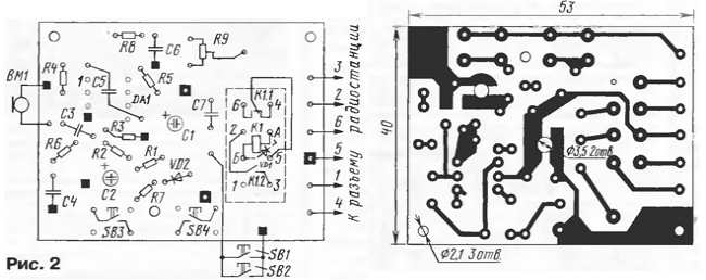
The foil under the parts is used only as a common wire. Connections to it "grounded" terminals of capacitors, resistors, etc. are shown in black squares. Before installing the DA1 chip, its pin 4 is bent to the side. Squares with a light dot in the center show jumpers connecting individual fragments of printed wiring to a common wire. In places where the conductors pass through this foil, protective circles with a diameter of 2 ... 2,5 mm should be etched (not shown in Fig. 2). Oxide capacitors are installed over holes with a diameter of 3,5 mm, and their leads are bent and soldered to the pads.
All fixed resistors are MLT-0,125, trimmer R9 is SPZ-386. Capacitors C1 and C2 - any oxide of suitable sizes, C3, C4, C6 and C7 - KM-6 or K10-176, C5 - KM-5 with multidirectional leads or similar (the capacitor is installed on top of the microcircuit). Relay K1 - RES47 for operating voltage 12 V with any passport. The VM1 dynamic microphone can be almost anything.
The mounted printed circuit board is secured with three M2 screws in a plastic housing box (Fig. 3). The pushers of the SB3 and SB4 buttons must be long enough to extend through the front panel of the housing. Experience has shown that a headset assembled in this way does not require any additional shielding.

The cable connecting the device to the radio station can be very short - 0,3...0,5 m. It is not difficult to make it yourself. Five soft conductors in fluoroplastic insulation are inserted into the shielding braid and the whole thing is pulled into a polyvinyl chloride tube with a diameter of 5...6 mm. The length of the cables to the SB1 and SB2 buttons (two conductors in a thin PVC tube) is practically unlimited.
The most expensive part of the headset (not counting the microphone) will be its only proprietary part - a connector for connecting to a radio station.
The designs of SB 1 and SB2 - desktop button and foot pedal - can be very different. As the contact pair itself, it is recommended to use a button in which the closure occurs with a click, for example, PKN-150-1.
Setting up the device is easy. You just need to install resistor R9 in a position that will correspond to the best modulation of the signal - not too small or, conversely, excessive with distortion and “overshoot” of the signal into adjacent channels. This is done based on feedback from correspondents. If in this case the R9 slider is in the extreme position, then by selecting the resistor R4, the gain of the operational amplifier is increased or decreased so that the desired gain corresponds to the position of the R9 slider that is more convenient for precise adjustment.
Author: Yu.Vinogradov, Moscow
 See other articles Section Civil radio communications.
Read and write useful comments on this article.
<< Back
<< Back
 Latest news of science and technology, new electronics:
Air trap for insects
01.05.2024
Agriculture is one of the key sectors of the economy, and pest control is an integral part of this process. A team of scientists from the Indian Council of Agricultural Research-Central Potato Research Institute (ICAR-CPRI), Shimla, has come up with an innovative solution to this problem - a wind-powered insect air trap. This device addresses the shortcomings of traditional pest control methods by providing real-time insect population data. The trap is powered entirely by wind energy, making it an environmentally friendly solution that requires no power. Its unique design allows monitoring of both harmful and beneficial insects, providing a complete overview of the population in any agricultural area. “By assessing target pests at the right time, we can take necessary measures to control both pests and diseases,” says Kapil ... >>
The threat of space debris to the Earth's magnetic field
01.05.2024
More and more often we hear about an increase in the amount of space debris surrounding our planet. However, it is not only active satellites and spacecraft that contribute to this problem, but also debris from old missions. The growing number of satellites launched by companies like SpaceX creates not only opportunities for the development of the Internet, but also serious threats to space security. Experts are now turning their attention to the potential implications for the Earth's magnetic field. Dr. Jonathan McDowell of the Harvard-Smithsonian Center for Astrophysics emphasizes that companies are rapidly deploying satellite constellations, and the number of satellites could grow to 100 in the next decade. The rapid development of these cosmic armadas of satellites can lead to contamination of the Earth's plasma environment with dangerous debris and a threat to the stability of the magnetosphere. Metal debris from used rockets can disrupt the ionosphere and magnetosphere. Both of these systems play a key role in protecting the atmosphere and maintaining ... >>
Solidification of bulk substances
30.04.2024
There are quite a few mysteries in the world of science, and one of them is the strange behavior of bulk materials. They may behave like a solid but suddenly turn into a flowing liquid. This phenomenon has attracted the attention of many researchers, and we may finally be getting closer to solving this mystery. Imagine sand in an hourglass. It usually flows freely, but in some cases its particles begin to get stuck, turning from a liquid to a solid. This transition has important implications for many areas, from drug production to construction. Researchers from the USA have attempted to describe this phenomenon and come closer to understanding it. In the study, the scientists conducted simulations in the laboratory using data from bags of polystyrene beads. They found that the vibrations within these sets had specific frequencies, meaning that only certain types of vibrations could travel through the material. Received ... >>
| Random news from the Archive The path to a healthy heart is through the intestines.
30.12.2015
It is possible to keep the heart and blood vessels healthy if the gastrointestinal microflora is kept under control, researchers from the Cleveland Clinic found out. Microflora, as we all know, helps digest food and thus actively interferes with metabolism. Through the breakdown products of various substances, bacteria can affect almost all body systems. One of the molecules that gut microbes actively work with is called choline, which is especially abundant in meat and eggs. Bacteria turn it into trimethylamine, which, once in the liver, undergoes further chemical metamorphoses and as a result, trimethylamine oxide is obtained from it. It is associated with cardiovascular disease in humans, which was indirectly confirmed in experiments on animals in which it increased the risk of atherosclerosis. That is, it turns out that damage to blood vessels begins with bacteria that process choline from our food.
Stanley Hazen and his colleagues discovered that a structural analogue of choline called DMB (3,3-dimethyl-1-butanol) inhibits bacterial enzymes that produce dangerous trimethylamine. Moreover, the effect was the same both with bacteria living in mice and with bacteria living in humans. If mice were kept on a high choline diet (and the animals themselves were predisposed to atherosclerosis), but at the same time they were given DMB, then the risk of atherosclerosis decreased in them: the level of atherogenic compounds in the blood fell, and plaques did not form on the walls of blood vessels.
DMB is found in olive oil and red wine, and by itself it is quite harmless: mice that were given it in a purified form felt fine four months after that. It should also be noted that DMB is harmless to the intestinal microflora, and in general it breaks down and is excreted from the body rather quickly. All in all, it looks like the perfect prophylactic: take DMB with food and you'll have healthy vascularity. However, there is no guarantee that microbes that are regularly treated with it will not find a way to adapt to such a new "external factor" - trimethylamine is used by some bacteria as an energy source, and they may well learn to get it again even in the presence of an enzyme inhibitor.
On the other hand, it is not known what will happen with long-term use of DMB. The authors themselves note that they noticed some changes in the ratio of microbial species in the intestines of mice, although such changes were extremely minor. Whether the same thing will happen to the human microflora, and whether this may lead to some side effects, will become clear only after new experiments.
|
Other interesting news:
▪ High-speed network will unite scientists from China, Russia and the USA
▪ Fujitsu F074 Waterproof Android Smartphone
▪ Mobile phone recognizes the owner
▪ Rarest eye color revealed
▪ Light-eating cyborg bacteria
News feed of science and technology, new electronics
 Interesting materials of the Free Technical Library:
▪ section of the site Riddles for adults and children. Article selection
▪ article Oh holy simplicity! Popular expression
▪ article Where and when did the first coffee house appear in Europe? Detailed answer
▪ article Use of gas burners in open wells of telephone communication. Standard instruction on labor protection
▪ article Automatic humidity controller. Encyclopedia of radio electronics and electrical engineering
▪ article Weightlessness and vegetable oil. physical experiment
Leave your comment on this article:
 All languages of this page
Home page | Library | Articles | Website map | Site Reviews

www.diagram.com.ua
2000-2024


 Arabic
 Bengali
 Chinese
 English
 French
 German
 Hebrew
 Hindi
Hindi Italian
 Japanese
 Korean
 Malay
Malay Polish
 Portuguese
 Spanish
 Turkish
 Ukrainian
 Vietnamese