|
|


 Arabic
 Bengali
 Chinese
 English
 French
 German
 Hebrew
 Hindi
Hindi Italian
 Japanese
 Korean
 Malay
Malay Polish
 Portuguese
 Spanish
 Turkish
 Ukrainian
 Vietnamese
|
ENCYCLOPEDIA OF RADIO ELECTRONICS AND ELECTRICAL ENGINEERING Transceiver protection device. Encyclopedia of radio electronics and electrical engineering
Encyclopedia of radio electronics and electrical engineering / Civil radio communications There are times when transceivers fail due to improper connection to the power supply or a sudden increase in voltage. The proposed device will help protect the equipment in these cases. The statistics of transceiver equipment repairs show that up to 30% of failures are caused by power failures. Typical emergencies include excess supply voltage (overvoltage) and non-observance of its polarity (polarity reversal). Some users manage to create a combination of these situations in some mysteriously incomprehensible way. It should be emphasized that the vulnerability of the radio station increases dramatically if a non-standard (including home-made) fuse and a power source with an unreasonably large current margin are used. In such cases, the internal protection of the transceiver turns out to be ineffective and the consequences of accidents become very serious, and sometimes even catastrophic. The inevitable mass failure of expensive and scarce components makes the restoration of a "killed" transceiver unprofitable. In case of accidents, various semiconductor devices are primarily damaged - diodes, transistors, integrated circuits. Their characteristics may change, breakdown or breakage of transitions, thermomechanical destruction of the case may occur. Resistors, winding products, backlight lamps fail. Swelling or explosion of oxide capacitors, delamination and burnout of printed conductors, charring of board sections, deformation of thermoplastic parts can occur. The entire collection of failures is taken from practice. Emergencies occur under the following circumstances: inept actions of a novice user, accidental error or negligence of a trained operator, intentional harm by an unauthorized person, technical malfunction of the power supply system. Unfortunately, no owner of a radio station is immune from such risks. Therefore, the idea arose to develop a device for reliable protection of the transceiver in emergency situations. The device blocks the power supply of the radio station when an abnormal voltage is received in the range from -50 to +50 V. It also has other useful properties, for example, it does not create a voltage drop in the transceiver power circuit, and also does not require the mandatory use of a fuse. As for the speed of protection, it is not worse than 2 ms and depends on the nature of the emergency. The scheme of the protection device is shown in fig. one.
When a voltage of positive polarity with a level of less than 10 V arrives at the input of the device, a current flows through the VD1R1K1VT1 circuit, but it is not enough to operate relay K1. At an input voltage of 10 ... 15 V, the relay is activated and supplies power to the transceiver. If during operation the voltage exceeds 15 V, then the zener diode VD2 will begin to conduct current, which will open the thyristor VS1. The voltage at the anode of the thyristor will drop, the transistor VT1 will close and the winding of the relay K1 will be de-energized. Since it is not shunted by anything, the release of the relay contacts will occur in a minimum time (actually 0,5 ... 2 ms). As a result, the transceiver will be disconnected from the increased voltage source. The Zener diode VD3, the use of which is optional, cuts off the short surge that is possible at a very high rate of voltage rise. In the event that an emergency high voltage arrives at the input of the device abruptly from the zero level, then it will not reach the transceiver at all, since the electronic "latch" VD2VS1VT1 will react several orders of magnitude faster than the K1 relay has time to operate. In the event of a polarity reversal, the negative polarity voltage will also not be supplied to the transceiver, since the relay will not work due to the VD1 diode, which will be closed by reverse voltage. After the emergency operation of the protection, the return to the initial state is carried out by briefly removing the input voltage. Two versions of the design of the device were made. In the first one, the details of the device are mounted inside the K1 relay case, which is used as the KUTs-1 relay (passport RA.362.900) from domestic color TVs. It has a winding resistance of 560 Ohm and operates at a voltage of about 5 V. The overall dimensions of the device (45x45x15mm) allow it to be placed inside the transceiver or outside on the cover. Another option is also very convenient - in a plastic cylindrical container from photographic film. The container has a diameter of 30 and a length of 50 mm. The finished product is filled with epoxy compound and installed in the break of the transceiver's power cord (similar to an impulse noise filter). Here, a more compact relay RES47 (passport RF4.500.409) with a winding resistance of 175 ohms is used. In this case, the resistor R1 must have a resistance of 110 ohms. Any other relays that operate at a voltage of 5 ... 6 V and are capable of switching a current of at least 3 A are also suitable (for example, TTI's TRC series relays). Transistor VT1 can be replaced by current keys of the KR1014, KR1064 series with indexes A, B or their analogues ZVN2120, VN2410. Instead of the VD1 diode, any other one with a forward current of at least 0,3 A and a reverse voltage of at least 400 V, for example, KD209A, is suitable. Zener diode VD2 can be replaced with D814 or KS515A. Thyristor VS1 can be with indices E-I, and it is desirable to use specimens selected for maximum sensitivity. The adjustment of the device begins with the selection of the resistor R1, achieving the operation of the relay at an input voltage of 9,5 ... 10 V. Then, slowly and smoothly increasing the voltage, make sure that the relay releases at 14,5 ... 15 V. If necessary, then the cutoff voltage can be changed by selecting the zener diode VD2. The author tested the ALAN-78 PLUS CB transceiver equipped with the proposed protection device. The test procedure simulated a series of the most dangerous accidents, namely a combination of polarity reversal and overvoltage. In addition, a factor aggravating the accident was deliberately introduced - instead of a regular fuse with a nominal value of 2 A, a thick wire jumper was installed. Under normal conditions, such, one might say, "lawlessness" guarantees extensive and irreversible destruction of the electronic elements of any transceiver. During the tests, the device was repeatedly connected to current sources (PS-30, B5-48, B5-71 power supplies, OSM-220/36 V transformer), which had the following parameters: -13,8 V (32 A); +16 V(10A);-16V(10A); + 30 V (10 A); -30 V (10 A); -36 V (50 Hz, 5 A); +50 V (2 A); -50 V (2 A). Each test voltage was applied to the transceiver automatically using a software device operating according to the cyclogram shown in the table.
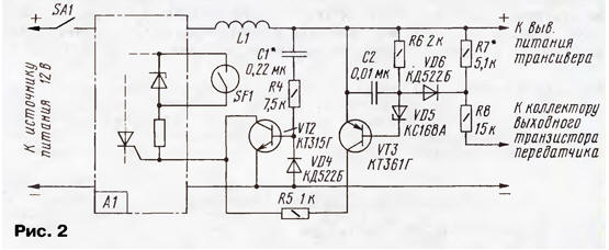
An extended test mode made it possible to simulate emergency situations of various durations and, along the way, to check the stability of protection against transients. If each fact of applying abnormal voltage to the transceiver is considered as an emergency situation, then it is easy to calculate that their total number was 688. Nevertheless, such a crushing effect did not cause any harm to the radio station. With the control supply of the rated voltage (+13,2 V), the device turned on and showed full performance. This test result testifies to the reliability of the device and allows it to be classified as "fool-proof". If the device is somewhat more complicated, it can provide additional protection for the current consumption and against an emergency increase in the RF voltage at the collector of the output transistor of the transmitter. Such an increase is possible with a mismatch of the antenna-feeder path or excitation of the output stage. The scheme of this option is shown in Fig. 2.
Current protection (overload and short circuit) is carried out using the SF1 reed switch with the L1 coil located on it. When the current consumed by the transceiver increases above the set value, the electromagnetic field of the coil becomes sufficient to close the magnetically controlled contact. Since the reed switch is connected in parallel to the VD2 zener diode, an emergency shutdown of the device occurs similar to the situation with overvoltage. Elements VT2, C1, R4, VD4 form a zone of temporary insensitivity of protection to the inrush current that occurs at the moment the transceiver is turned on. For the radio station ALAN-78PLUS, this time is 22 ms and can be adjusted by selecting the capacitor C1. When working with the device (Fig. 2), you must first turn on the transceiver, and then the SA1 toggle switch. Setting the current protection to a level of 2 ... 3 A is reduced to selecting the number of turns of the L1 coil, consisting of 4-8 turns of PEL 0,5 wire (roughly) and moving it along the reed switch (finely) followed by fixing with hot melt adhesive. With a mismatched load (for example, a break in the antenna-feeder path), the RF voltage at the collector of the output transistor of the transmitter increases, which is fraught with a breakdown of its transitions. However, in this case, the zener diode VD5 begins to conduct current, which opens the transistor VT3. The positive voltage from the collector of the transistor is supplied to the control electrode of the thyristor VS1. The device then shuts down in the same way as other emergencies. Resistor R7 is selected in such a way that the transceiver turns off when the transmitter is operating on the antenna equivalent of 150 ohms, which corresponds to SWR-3. The emitter junction of the transistor VT2 (see Fig. 2) must be shunted with a resistor with a resistance of about 10 kOhm. Author: A.Sokolov, Moscow
A New Way to Control and Manipulate Optical Signals
05.05.2024 Primium Seneca keyboard
05.05.2024 The world's tallest astronomical observatory opened
04.05.2024
▪ Icebreakers must sail backwards ▪ Innovative lidar Velodyne VLS-128 ▪ Dark matter can heat planets from the inside ▪ Supermassive black hole discovered
▪ site section Power supply. Article selection ▪ article Aesopian language. Popular expression ▪ article How did Coca-Cola appear? Detailed answer ▪ article Storekeeper. Job description ▪ article AF power amplifier (80 watts). Encyclopedia of radio electronics and electrical engineering ▪ article Cigarettes from nowhere. Focus Secret
Home page | Library | Articles | Website map | Site Reviews
www.diagram.com.ua |


 Leave your comment on this article: