|
|
ENCYCLOPEDIA OF RADIO ELECTRONICS AND ELECTRICAL ENGINEERING A matching device for a 144/27 MHz transverter. Encyclopedia of radio electronics and electrical engineering
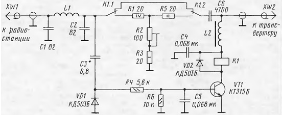
Encyclopedia of radio electronics and electrical engineering / Civil radio communications The proposed device is designed to work together with the transverter described in the article "Stationary FM transverter 144/27 MHz"(" Radio ", 2000, No. 2, pp. 60, 61). It allows you to improve its performance. The operation of the transverter showed that when it is docked with CB radio stations, a problem arises due to the fact that these radio stations, as a rule, have an output power of 4 W or more. Although the transverter can operate with input power up to 6 W, pumping it with a strong signal often results in out-of-band emissions. To eliminate this shortcoming, it is necessary to reduce the input power supplied to the transverter. Some CB radio stations have this feature. However, most of them do not. The way out of this situation may be to install a special matching device between the radio station and the transverter. This device should reduce the transmit power ("TX") to the transverter to an optimum level. This can be done, for example, using a simple resistive attenuator. But in this case, the reception signal will be weakened, which can lead to a loss of sensitivity, and, in addition, the power entering the antenna in the CB band will decrease. Therefore, such an attenuator must be made automatic so that it is connected only when working in conjunction with a transverter in the "TX" mode. A diagram of such a device is shown in the figure. It contains a low-pass filter with a cutoff frequency of about 40 MHz on C1L1C2 elements, which additionally suppresses signal harmonics during transmission and attenuates the signal of the transverter's local oscillator during reception. An adjustable switchable attenuator is assembled on resistors R1-R3, R5 and relay K1. The control unit is assembled on the transistor VT1 and the diode VD1. The relay is powered from the transverter via the connecting cable and L2 choke.
When the transverter is turned off, power is not supplied to the matching device and the attenuator is turned off, so the signal passes without loss to the transverter and from it to the CB antenna. When the transverter is turned on, the supply voltage is supplied to the device. In the receive mode "RX" transistor VT1 is closed, so the relay is de-energized and the attenuator is disabled. When switching to the "TX" mode, the transmitter signal through the capacitor C3 enters the diode VD1, is rectified and fed to the base of the transistor VT1, it opens and the relay K1 is activated. With its contacts, it connects an attenuator, and the transmitter signal at the input of the transverter is attenuated. The trimming resistor R2 can be used to adjust the attenuation within 5 ... 10 dB, with a satisfactory agreement. At the end of the transmission, the transistor closes, the relay de-energizes and the attenuator turns off. The device can use transistors of the KT315, KT312, KT3102 series with any letter index. Diode VD1 - series KD521, KD522; VD2-any low-power rectifier. Capacitors - K10-17, KM. Trimmer resistor R2 - SPO, SP4, constants - MLT, S2-33. Resistor R1 is made up of two MLT-2 connected in series, 10 ohms each. Relay K1 - RES47 with a winding resistance of 600 ohms (passport RF4.500.417). Coil L1 is wound with wire PEV-2 0,8 on a mandrel with a diameter of 4,5 mm and contains 10 turns; L2 - inductor DM-0,1 with an inductance of 100 μH or more, it can be wound on a ferrite ring 2000NN with a diameter of 5 ... 10 mm with a PEV-2 0,1 wire; the number of turns is 15-20. It is necessary to refine the transverter - between the XW1 socket and the SA1.1 switch contact it is necessary to install a capacitor with a capacity of 1000 cOpF (KM, K10-17), and install a DM-1 choke between the XW10 socket and the upper (according to the transverter circuit) output of the resistor R0,1 100 uH. Establishing the device is reduced to the selection of capacitor C3 until a stable operation of the relay is obtained. Author: I.Nechaev (UA3WIA)
A New Way to Control and Manipulate Optical Signals
05.05.2024 Primium Seneca keyboard
05.05.2024 The world's tallest astronomical observatory opened
04.05.2024
▪ Cheap way to produce nanoparticles ▪ Vaccination against hypertension ▪ Autonomous car turns the driver into an instructor ▪ Monitor ASUS ROG Strix XG43VQ
▪ section of the site Palindromes. Article selection ▪ article Negative impact of harmful substances on the environment. Fundamentals of safe life ▪ article Which writer suffered from paranoia, which later turned out to be justified? Detailed answer ▪ article Kalgan officinalis. Legends, cultivation, methods of application ▪ article Automotive tachometer. Encyclopedia of radio electronics and electrical engineering ▪ article Miraculous coincidence. Focus Secret
Home page | Library | Articles | Website map | Site Reviews www.diagram.com.ua |


 Arabic
 Bengali
 Chinese
 English
 French
 German
 Hebrew
 Hindi
Hindi Italian
 Japanese
 Korean
 Malay
Malay Polish
 Portuguese
 Spanish
 Turkish
 Ukrainian
 Vietnamese

 Leave your comment on this article: