|
|


 Arabic
 Bengali
 Chinese
 English
 French
 German
 Hebrew
 Hindi
Hindi Italian
 Japanese
 Korean
 Malay
Malay Polish
 Portuguese
 Spanish
 Turkish
 Ukrainian
 Vietnamese
|
ENCYCLOPEDIA OF RADIO ELECTRONICS AND ELECTRICAL ENGINEERING Car tachometer
Encyclopedia of radio electronics and electrical engineering / Automobile. Electronic devices Recently, the problem of controlling the speed of a car engine has become very relevant. The previously proposed circuits [1, 2] have a number of disadvantages associated with a large number of elements, a large current consumption, and the ability to control the engine speed only in digital form.
Another version of the tachometer is proposed, providing: - turnover control both in digital and visual form;
- minimum current consumption, depending solely on the LEDs used; - acceptable accuracy and ease of setup when using five IC series 176 and 561. The schematic diagram of the device is shown in Fig.1. The signal from the speed sensor B1 goes to the pulse shaper, assembled on the elements DD6.1; DD6.2, R2, R3. Elements C4. Rl. VD14, VD15 limit the sensor signal to 9 V.
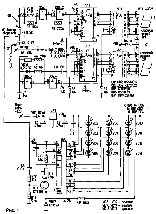 The generated signal is fed to the input of the counter, assembled on the elements DD1, DD2. Decoders on ICs DD3, DD4 convert the BCD code of the counters into the code of a seven-segment indicator, and also provide intermediate memory, thereby eliminating the flickering of digits during counting. The operation of the device is controlled by a generator on the elements DD6.3, R5 ... R7, C7, VD16. The shape of the output pulses of the generator is shown in Fig.2. 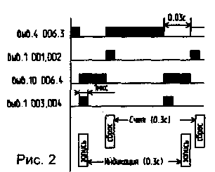
After power is applied, a short "write" pulse writes to the IC DD3. DD4 random information. Next, the counters DD1, DD2 are reset by a short "reset" pulse with a duration of about 1 μs, formed by the chain C8, R8, and the pulses from the speed sensor are counted for a period of 0,3 s.
0,03 s before the expiration of this time, the contents of the counters DD3, DD4 are recorded in DD1, DD2 with simultaneous indication of the current engine speed on the HG1 indicator. The operation is provided by a short pulse (=1 μs) formed by the chain C9, R9.
Visual perception of the number of revolutions gives a device made on the IC DD5. The higher the rpm, the higher the bar of lit LEDs. Green zone - normal speed, yellow - critical, red - limit. As DD5, a polycomparator IC K1003PP1 was used. The scheme of its inclusion and the principle of operation are described in detail in the literature [17]. The height of the column of luminous LEDs depends on the voltage at pin 5 DDXNUMX, which depends on the speed.
The frequency-voltage conversion is provided by the elements VT1, R10 ... R13, C5, C6.
Construction and details Possible replacement of the elements indicated in the diagram: HG1 - for any two LED indicators with a common cathode of the ALS324A type; DD3, DD4 - on K176IDZ; DD1, DD2 - on K561IE11 (but you will have to redo the circuit and the board a little); VT1 - KT315A...G, KT3102; KT503; KT645; K.T634. The speed sensor is 50...70 turns of wire PEV-1 00.5...1,0 mm, laid turn to turn on a high-voltage wire from the reel to the distributor.
One end of the sensor is connected to the circuit, the other is isolated and not connected anywhere. All electrolytic capacitors must be designed for a voltage of at least 16 V. DD6 of the K561TL1 series is not recommended to be replaced. DA1 is better to install on a small finned radiator. VD2...VD13 - any LEDs (rectangular or round) of the corresponding color. The front panel of the tachometer is shown in Fig.3. 
Setting. A signal with a frequency of 100 Hz is applied to point A. By adjusting the resistor R3, a stable signal is achieved at the output of DD6.2. By adjusting the resistor R5, the indicator reading is 3.0, which corresponds to 3000 rpm. Further, according to the formula below, the minimum and maximum revolutions are determined, i.e. their equivalent frequencies.
N=2n/60,
where N is the frequency of ignition pulses (point A); n - frequency of revolutions of the motor shaft.
By applying a frequency corresponding to the maximum speed, the resistor R11 achieves the ignition of VD13. Now, by applying the frequency of minimum revolutions, the ignition of the VD2 LED is controlled. If it does not ignite, pick up R10. This completes the setup. If you do not like a column of burning LEDs, you can offer a "moving dot". In this case, VD2...VD13 is connected according to [З]. 
If switch S1 is provided as shown in Fig. 4, DD5 can perform the function of both a tachometer and an indicator of the voltage of the car's on-board network. Elements VD* and R* provide a voltage change at pin 17 DD5 in the range of O ... 6 V with changes in voltage in the vehicle's on-board network. The range of voltage changes depends on VD* (see table). When tuning with R *, the correct readings of DD5 are achieved.
Literature 1. Kravchuk V. Tachometer. - Radio amateur, 1997, N 6, S. 31.
2. Rubtsov V. Digital tachometer. - Radio amateur, 1997, N 5, S.24. 3. Shustov M. The use of polycomparator microcircuits in communication technology.-Radio amateur, 1997.N6, p.13. 4. Digital tachometer. - Radio. 1993, N9, C.28-29. 5. Biryukov S.A. Digital devices on the MOS-IC. Author: A. Chastov, 225734, Brest region, Pinsk district. p / o Pogost-Zagorodsky, fish farm "Polesie", Radio amateur No. 12 1998; Publication: cxem.net
See other articles Section Automobile. Electronic devices
Artificial leather for touch emulation
15.04.2024 Petgugu Global cat litter
15.04.2024 The attractiveness of caring men
14.04.2024
▪ site section Welding equipment ▪ Stereophile magazines (annual archives) ▪ book Journey to an amazing world. Arakcheev Yu., 1989 ▪ article Why does Lara Croft have such big breasts? Detailed answer ▪ article Plain solid and liquid soap. Simple recipes and tips ▪ article Color reactions with glucose. Chemical experience ▪ reference book Service menus of foreign TVs. Book #7
Home page | Library | Articles | Website map | Site Reviews
www.diagram.com.ua |

 Leave your comment on this article: