|
|


 Arabic
 Bengali
 Chinese
 English
 French
 German
 Hebrew
 Hindi
Hindi Italian
 Japanese
 Korean
 Malay
Malay Polish
 Portuguese
 Spanish
 Turkish
 Ukrainian
 Vietnamese
|
ENCYCLOPEDIA OF RADIO ELECTRONICS AND ELECTRICAL ENGINEERING Refinement of the power supply SY-002-5-12. Encyclopedia of radio electronics and electrical engineering
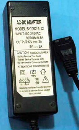
Encyclopedia of radio electronics and electrical engineering / Power Supplies To connect hard drives, SSDs, CD-ROM readers and recorders to digital multimedia devices, you can use JSB2-IDE/SATA controllers connected to a free JSB1.1/JSB2/JSB3 port on a computer, laptop, tablet computer, DVD- player, TV. This method is convenient to use for infrequent connection of various storage devices, their testing and repair. For this purpose, two such Chinese-made controllers were purchased. When testing the device, after 10 minutes, the included power supply unit (PSU) model SY-002-5-12 (Fig. 1) began to emit the smell of burnt plastic, while its case became very hot (the old Quantum Fireball hard drive was the load) . After 10 hours of further testing, it was decided to modify the named PSU. This decision was facilitated by the fact that the available three power supplies, also designed for a load current of 2 A for both output voltages (5 and 12 V) and designed to power containers for external hard drives, practically did not heat up.
The plastic case of the PSU, which consists of two halves held together with a few drops of glue, is easy to disassemble with a sharp knife and a wide flat screwdriver. After inspecting the installation, which did not reveal any failures under the action of Using the temperature of the elements, a circuit diagram of the PSU was drawn up on the basis of the printed circuit board, the analysis of which formed the basis of the refinement described below. The scheme of the modified device is shown in fig. 2. The numbering of the elements corresponds to that indicated on the board, the reference designations of new parts begin with the prefix 1, their numbering continues the factory one. As you can see, the circuit of the device as a whole is typical for a pulsed power supply unit with a transistor converter. The main difference is that instead of the traditional single bipolar transistor, an analogue of a low-power trinistor, assembled on transistors Q2, Q3, is installed in the output voltage stabilization and overload protection circuit.
The powerful high-voltage field-effect transistor CEF02N6A (Q1) used in the PSU has a relatively high open channel resistance, so a more powerful and reliable STP4NK60ZFP with a built-in protective zener diode was installed instead. Resistor R5 (1,5 kOhm) is replaced by a 910 Ohm resistor, capacitor C4 (2200 pF) is replaced by a 3300 pF capacitor. There was no capacitor C2 on the PSU board; a high-voltage ceramic capacitor with a capacity of 1500 pF with a rated voltage of 2000 V was installed by selecting the lowest current consumption. Instead of the 1N4007 (D6) diode, which caused doubts in appearance, an ultrafast JF4007 diode was used. The 1R1 resistor is connected to the break in the winding circuit II of the pulse transformer T15, the connection point of the resistor R4 has been changed: its upper (according to the diagram) output is now connected not to the connection point of the resistor R6 with the diode D6 and the capacitor C2, but to the positive plate of the capacitor C1, and its value not 680 kOhm, but 1 MΩ. After these changes, the current consumed by the unit with the connected load decreased by 20%. To improve the reliability of the PSU, several more improvements were also made. In parallel with the oxide capacitor C5, a ceramic 1C9 is installed, the miniature capacitor CF (2200 pF x 1000 V) is replaced by a high-voltage ceramic conventional size with a capacitance of 1000 pF with a nominal voltage of 2000 V. PSU starting current. If there are no significant installation restrictions, then it is advisable to connect this thermistor in series with the F1 fuse. To reduce the sensitivity of the PSU to impulse noise, a 4L1 choke and a 1RJ1 varistor are additionally installed. Oxide capacitors C6 and C7 with a capacity of 470 uF each are replaced by capacitors with a capacity of 1500 uF, and in parallel with them (soldered directly to their terminals) ceramic surface-mounted capacitors (1C11 and 1C10, respectively). At the same time, it turned out that C6 was partially faulty at the time of revision: the leakage current was about 100 mA at 16 V, the output voltage ripple was 250 mV. After its replacement, the ripple amplitude with the connected load decreased to 30 mV. Replacement oxide capacitors must be rated for ambient temperatures up to 105 оC. To protect against damage to devices connected to this PSU in the event of a malfunction or impulse noise, a protective diode 1D10 and a zener diode 1D11 are installed in the network. A brass heat sink with a cooling surface area of 9 cm3 is soldered to the cathode terminal of the Schottky diode D2, this will allow using the PSU to power and charge the batteries of tablet computers. A 8R1 resistor is installed in parallel with the R16 resistor, which reduced the PSU output voltage in idle mode from 5,36 to 5,2 V. The green LED (unfortunately, barely noticeable) was replaced by a red glow LED (presumably the L-1553 series) . Inductor 1L1 - small-sized industrial production, wound on an H-shaped ferrite magnetic core, winding resistance to direct current - 1 Ohm. Any similar inductance up to 100 μH and DC winding resistance up to 3 ohms will do. All newly installed resistors are small-sized, of any type and dissipation power indicated on the diagram. Varistor FNR-07K471 (RU1) can be replaced by any of FNR-10K471, FNR-10K561, TVR10471, MYG10-471, INR14D471, INR10D511. Before installation, a piece of heat-shrinkable tube is put on its body. The same tube is used to insulate the CF capacitor. The thermistor SCK083 (1RK1) with a resistance of about 12 ohms at room temperature can be replaced by any with a negative TCR and a resistance of 4 ... 33 ohms. Instead of the UF4007 (D6) diode, any of the UF4006, FR157, 1N4937GP, 1 N5399, KD247D, KD258D diodes is suitable, and instead of the RbKE15A protective diode, 1.5KE15A or a zener diode 1 N5352. The view of the modified circuit board is shown in fig. 3.
To cool the field-effect transistor Q1, the manufacturer used an aluminum heat sink in the form of a plate measuring 25x15x1 mm (it is visible in the photo). The temperature of the transistor case with this heat sink, even with the PSU case open, reached 90 оC. A slightly better result was achieved after installing the transistor on an L-shaped aluminum heat sink with dimensions of 55x22x2 mm (the latter was located in such a way that its most part was pressed against the top cover of the device case) - the temperature of the transistor case dropped to 56 оC. This is a satisfactory result, since more was expected, perhaps the best could not be achieved due to the poor quality of the pulse transformer T1. To lower the air temperature inside the PSU case due to natural ventilation, 70 holes with a diameter of 3 mm were drilled in its side walls, and real holes with a diameter of 1,8 mm were drilled in the upper wall, in places where ventilation holes were simulated. Four rubber feet 4 mm high are glued to the bottom wall of the PSU case. During operation, do not place the power supply unit and the device connected to it in a "shelf". For additional protection of the device powered by the block and improving the quality of its power supply, you can use the filter described in the author's article "Power Filter for HDD" ("Radio", 2014, No. 2, pp. 26-28). Before connecting and disconnecting devices powered by the unit, disconnect the PSU from AC 230 V. Author: A. Butov
Machine for thinning flowers in gardens
02.05.2024 Advanced Infrared Microscope
02.05.2024 Air trap for insects
01.05.2024
▪ Found the most radioactive place on Earth ▪ Augmented Reality Contact Lenses ▪ Plastic road made from recycled bottles ▪ Creative people enjoy wasting time.
▪ section of the website job descriptions. Article selection ▪ article How did British pilots make V-1 rockets fall in the place they needed? Detailed answer ▪ article Bodiak garden. Legends, cultivation, methods of application ▪ article What are radio waves? Encyclopedia of radio electronics and electrical engineering
Comments on the article: M. Sergey A very necessary article. I repeated almost all the improvements - the characteristics improved, the temperature dropped significantly. Thanks to the author!
Home page | Library | Articles | Website map | Site Reviews
www.diagram.com.ua |


 Leave your comment on this article: