|
|


 Arabic
 Bengali
 Chinese
 English
 French
 German
 Hebrew
 Hindi
Hindi Italian
 Japanese
 Korean
 Malay
Malay Polish
 Portuguese
 Spanish
 Turkish
 Ukrainian
 Vietnamese
|
ENCYCLOPEDIA OF RADIO ELECTRONICS AND ELECTRICAL ENGINEERING Line voltage signaling device
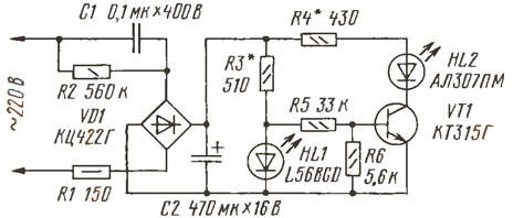
Encyclopedia of radio electronics and electrical engineering / Surge Protectors It is useful to integrate such a device into a power switch or plug socket, which will make it easier to find them in the dark. Or you can make it in the form of an attachment to an electrical device, so that there is light information about their inclusion in the network. The signaling device (see figure) is made on the basis of a flashing LED HL1, which, together with the cascade on the transistor VT1, forms a simple two-phase generator of light pulses. The device is powered from an alternating current network through a transformerless rectifier made on a quenching capacitor C1 and a diode bridge VD1. Resistor R1 limits current surges through the bridge diodes, and R2 discharges the capacitor after disconnecting the alarm from the network.
The filter capacitor C2 is charged to a voltage of approximately 6 V. It is supplied, in particular, through the limiting resistor R3 to the flashing LED HL1, the flashes of which follow at a frequency of approximately 2 Hz. During the LED flash, the voltage at the base of the transistor, supplied through the divider on resistors R5, R6, does not exceed 0,55 V, which is not enough to open the transistor. But as soon as the blinking LED goes out, the voltage at its anode, and therefore at the base of the transistor, increases. The transistor opens and the HL2 LED lights up. Thus, the LEDs alternately light up at a frequency determined by the characteristics of the HL1 LED. The device uses a foreign flashing green LED with a diameter of 5 mm and a luminous intensity at a rated current of 20 mcd. The L56BID red LED or any other flashing LED with a diameter of 3, 5 or 10 mm is also suitable. The transistor can be any of the KT315, KT342, KT503, KT3102 series with a base current transfer coefficient of at least 100. The KTs422G diode bridge can be replaced with KTs407A, KD906A or four diodes KD102B, KD221V. KD221G, any of the KD209 series. Capacitor C1 - series K73-16, K73-17, K73-21 for a voltage of at least 400 V, C2 - K50-35 or a small-sized foreign analogue for a voltage of 16 V. It is advisable to use resistor R1 of series P1-7, P1-25, acceptable instead, install an incandescent lamp at a voltage of 12-24 V and a current of 0,1-0,15 A. The remaining resistors are MLT of the appropriate power. It is advisable to place the alarm parts on a board measuring 35x50 mm using any type of installation. To reduce the size of the device, capacitors can be installed lying in the slots of the board. LEDs are placed on the protective decorative cover of a switch, socket or the body of a set-top box for a household electrical appliance, gluing them with epoxy glue or Moment glue. For better adhesion of the glue to the base, the areas around the holes for installing LEDs on the inside should be treated with coarse sandpaper. It is, of course, possible to place the device inside an electrical appliance. In any case, the ambient temperature at the installation site of the board and LEDs should not exceed 60°C. To connect the device to the network and connect the LEDs to the board, it is better to use a multi-core MGTF wire. If the signaling device is mounted in a switch or in an internal wiring socket, then in order to insulate the board, in no case should it be wrapped with electrical tape or adhesive tape. It is better to use fiberglass or mica gaskets. It is also permissible to use a piece of fiberglass laminate for this purpose, calcined in the flame of a gas burner. After removing the foil, pre-firing is carried out in the open air. Greater brightness of the LEDs can be achieved by installing capacitor C1 with a capacity of 0,15 or 0,22 μF. In this option, it is advisable to use capacitor C2 for a higher voltage. Approximately the same brightness of the LEDs is set by selecting resistors R3 and R4 within 30% of the indicated values. If you have a stabilized 6 V power supply, it is advisable to conduct a preliminary test with it by applying voltage to capacitor C2. Attention! Structures galvanically connected to the network are dangerous to life due to possible electric shock. Therefore, when manufacturing, testing, setting up and operating them, one should remember to strictly adhere to electrical safety measures. Firstly, the body of the structure must be made of insulating material, and the structure itself is made in such a way as to prevent accidental contact with the exposed leads of conductors or parts. Parts of controls protruding outwards (switches, switches, variable resistors, etc.) must have handles made of insulating material. Secondly, when checking the operation of the structure, you should not touch any of its parts or circuits with your hands, and solder replaced parts only with the power plug removed from the socket. If the design is intended to control some kind of external load, first connect the load, and only then insert the power plug into the power outlet. Author: A.Leonidov, village of Kurba, Yaroslavl region
Artificial leather for touch emulation
15.04.2024 Petgugu Global cat litter
15.04.2024 The attractiveness of caring men
14.04.2024
▪ Japan dominates the OLED market ▪ This sweet word is meteorite
▪ site section Infrared technology. Article selection ▪ article Before the Greek calends. Popular expression ▪ article What is olive oil? Detailed answer ▪ article Working with Styrofoam. home workshop ▪ article Easy and Inexpensive Fence Paint. Simple recipes and tips
Home page | Library | Articles | Website map | Site Reviews
www.diagram.com.ua |

 Leave your comment on this article: