|
|


 Arabic
 Bengali
 Chinese
 English
 French
 German
 Hebrew
 Hindi
Hindi Italian
 Japanese
 Korean
 Malay
Malay Polish
 Portuguese
 Spanish
 Turkish
 Ukrainian
 Vietnamese
|
ENCYCLOPEDIA OF RADIO ELECTRONICS AND ELECTRICAL ENGINEERING Application of integrated voltage stabilizers KR142. Encyclopedia of radio electronics and electrical engineering
Encyclopedia of radio electronics and electrical engineering / Surge Protectors Microcircuits of the KR142 series are widely used in amateur radio designs. All of them are almost identical in scheme, contain a built-in load circuit protection device. They differ only in the maximum output current and the rated output voltage, which has one of the following values: 5, 6, 9, 12, 15, 20, 24 and 27 V. Your attention is invited to a selection of circuits of various voltage stabilizers, made using these microcircuits. Voltage stabilizer protected from damage by the discharge current of capacitors If there is a large capacitor in the output CH circuit, it is sometimes necessary to take measures to protect the microcircuit, that is, to prevent the capacitor from discharging through its circuits. The fact is that capacitors with a capacity of up to 10 microfarads or more, usually used in power circuits of devices, have low internal resistance, therefore, in the event of an emergency circuit of one or another circuit of the device, a current pulse occurs, the value of which can reach tens of amperes. And although this impulse is very short, its energy may be enough to destroy the microcircuit. The pulse energy depends on the capacitance of the capacitor, the output voltage and the rate of its decrease. To protect the microcircuit from damage in such cases, diodes are used. In the device made as shown in Fig. 2.10 diagram, the diode VD1 protects the DA1 chip from the discharge current of the capacitor C2, and the diode VD2 - from the discharge current of the capacitor C3 when the CH input is shorted. The most suitable for use in stabilizers are tantalum oxide capacitors, which (of course, with the necessary capacitance) have low impedance even at high frequencies: here a tantalum capacitor with a capacitance of 1 μF is equivalent to an aluminum oxide capacitor with a capacitance of approximately 25 μF.
MV with stepped switching The functions of the "switching" element in this device are performed by the transistor VT1 (Fig. 2.11). At the moment the power is turned on, the capacitor C3 starts charging, so the transistor is open and shunts the lower arm of the divider R1, R2. As the capacitor charges through the resistor R3, the transistor closes, the voltage at pin 8 of DA1, and therefore at the output of the device, increases, and after a while the output voltage reaches a predetermined level. The duration of the establishment of the output voltage depends on the time constant of the circuit R3, C3.
MV with increased stability output voltage As can be seen from the circuit in Figure 2.12, the difference between this CH and the previously considered ones (except for the absence of protective diodes and capacitor C3) is to replace the resistor R2 with a zener diode VD1. The latter maintains a more stable voltage at pin 8 of the DA1 chip and thereby further reduces voltage fluctuations at the load. The disadvantage of the device is the impossibility of smooth adjustment of the output voltage (it can only be changed by selecting the zener diode VD1).
MV with output voltage adjustable from 0 to 10 V On fig. 2.13 shows a diagram of a device whose output voltage can be adjusted from 0 to 10 V. The required value is set by a variable resistor R2 When its engine is set to the lower (according to the circuit) position (the resistor is completely removed from the circuit), the voltage at pin 8 of DA1 has a negative polarity, therefore the output voltage of CH is 0. As the slider of this resistor moves up, the negative voltage at pin 8 of the IC decreases and, with some resistance, becomes equal to the output voltage of the microcircuit. With a further increase in the resistance of the resistor, the output voltage of the CH increases from 0 to the maximum value. The disadvantage of the circuit is the need for an external voltage source of -10 V.
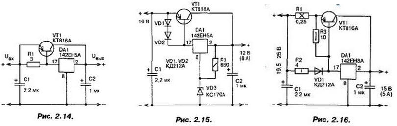
CH with external control transistors Microcircuits 142EN5, 142EN8, 142EN9, depending on the type, can supply current up to 1,5 ... power transistors). It is possible to facilitate the operation of the microcircuit in such cases by connecting an external control transistor to it. A schematic diagram of the basic variant of CH with an external control transistor is shown in fig. 2.14. With a load current of up to 180 ... 190 mA, the voltage drop across the resistor R1 is small, and the device operates in the same way as without a transistor. With a higher current, this voltage drop reaches 0,6 ... 0,7 V, and the transistor VT1 begins to open, thereby limiting a further increase in current through the DA1 microcircuit. It maintains the output voltage at a given level, as in a typical switch-on: with an increase in the input voltage, the input current decreases, and, consequently, the voltage of the control signal at the emitter junction of the transistor VT1, and vice versa. When using such a SN, it should be borne in mind that the minimum difference between the input and output voltages must be equal to the sum of the minimum voltage drop on the microcircuit used and the voltage of the regulating transistor. It is also necessary to take care of limiting the current through this transistor, since when it is shorted in the load, it can exceed the current through the microcircuit by a factor equal to the static current transfer coefficient of the transistor, and reach 20 A or even more. In most cases, such a current is enough for a day of failure not only of the control transistor, but also of the load. Schemes of possible variants of CH with current limitation through the regulating transistor are shown in fig. 2.15, 2.16, 2.17. In the first of them, this problem is solved by turning on parallel to the emitter junction of the transistor VT1 two diodes VD1, VD2 connected in series, which open if the load current exceeds 7 A. The stabilizer continues to work even with some further increase in current, but as soon as it reaches 8 A, it fires overload protection system. The disadvantage of the considered option is the strong dependence of the protection system operation current on the parameters of the transistor and diodes (it can be significantly weakened if thermal contact between the cases of these elements is ensured). Much less this drawback is manifested in another stabilizer (Fig. 2.16). Assuming that the voltage at the emitter junction of the transistor VT1 and the forward voltage of the diode VD1 are approximately the same, then the current distribution between the DA1 microcircuit and the regulating transistor depends on the ratio of the resistance values of the resistors R2 and R1. With a low output current, the voltage drop across the resistor R2 and the diode VD1 is small, so the transistor VT1 is closed and only the microcircuit works. As the output current increases, this voltage drop increases, and when it reaches 0,6 ... 0,7 V, the transistor begins to open, and more and more current begins to flow through it. At the same time, the microcircuit maintains the output voltage at a level determined by its type: when the voltage increases, its regulating element closes, thereby reducing the current flowing through it, and the voltage drop across the R2, VD1 circuits decreases. As a result, the voltage drop across the regulating transistor VT1 increases and the output voltage decreases.
If the voltage at the MV output decreases, the regulation process proceeds in the opposite direction. The introduction of a resistor R1 into the emitter circuit of the transistor VT1, which increases the stability of the CH operation (it prevents its self-excitation), requires an increase in the input voltage. At the same time, the greater the resistance of this resistor, the lower the overload response current depends on the parameters of the transistor VT1 and the diode VD1. However, with an increase in the resistance of the resistor, the power dissipated on it increases, as a result of which the efficiency decreases and the thermal regime of the device worsens. Author: Semyan A.P.
Artificial leather for touch emulation
15.04.2024 Petgugu Global cat litter
15.04.2024 The attractiveness of caring men
14.04.2024
▪ Hybrid iron with vacuum cleaner ▪ Dell UltraSharp 40 Curved Monitor ▪ RRAM memory chips 200 mm2 1 TB
▪ site section Low frequency amplifiers. Article selection ▪ article Comments are superfluous. Popular expression ▪ Which actor was forced to play in Harry Potter by his granddaughter? Detailed answer ▪ article Origanum vulgaris. Legends, cultivation, methods of application ▪ article Universal Cube. Focus Secret
Home page | Library | Articles | Website map | Site Reviews
www.diagram.com.ua |


 Leave your comment on this article: