|
|


 Arabic
 Bengali
 Chinese
 English
 French
 German
 Hebrew
 Hindi
Hindi Italian
 Japanese
 Korean
 Malay
Malay Polish
 Portuguese
 Spanish
 Turkish
 Ukrainian
 Vietnamese
|
ENCYCLOPEDIA OF RADIO ELECTRONICS AND ELECTRICAL ENGINEERING Another telephone watchman. Encyclopedia of radio electronics and electrical engineering
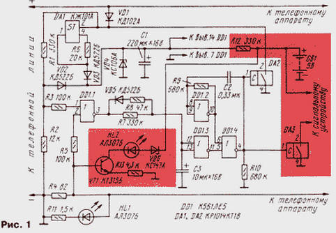
Encyclopedia of radio electronics and electrical engineering / Telephony Recently, the magazine "Radio" has addressed the topic of "telephone piracy" several times. The pages of the magazine published a description of several relatively simple designs that allow either to detect an unauthorized connection to a telephone line, or to block dialing from a "pirate" phone. The proposed article provides a description of another device. A diagram of a device that blocks a telephone line in case of illegal connection and emits an audible alarm is shown in fig. 1. In case of disconnection of the line going to the apartment, the device also gives a warning. An attacker will not be able to call both the "intercity" and the city phone. So that the disconnection of the line does not go unnoticed when the owner is not at home, we advise, for example, to agree with the neighbors by duplicating the signaling device.
The watchman can be made in two versions: with and without sound alarm. In the variant without sound signaling, the device is powered by a telephone line, and with an alarm - from a battery of galvanic cells. The elements required in the version with signaling are shown in fig. 1 on a colored background. First, consider the option without sound signaling - powered by a telephone line. In this case, the device only blocks the line in case of unauthorized connection. On the current stabilizer DA1 and the zener diode VD4, a power supply unit from the line is assembled. Key DA2 is designed to block the line. When the device is connected to the line with polarity, the VD1 diode passes current to the resistive divider R1R2. A high level occurs at pin 1 of the DD1.1 element, since at a voltage of 60 V in the telephone line, the voltage across the resistor R2 will be about 2,1 V, and the supply voltage of the microcircuit (set by the zener diode VD4) is 3,2 V. Diode VD2 protects the input microcircuits from increased voltage at the time of the call. The output of the element DD1.1 is low, the output of DD1.3 is high, and the multivibrator on the elements DD1.2, DD1.4 does not work. When you pick up the handset from the telephone set located in the apartment, current flows through the resistor R4. Because of this, the input 2 of the element DD1.1 will be high, and the input 1 will be low, as the voltage drops in the telephone line. The multivibrator also does not work, because the output of the DD1.1 element will still be low. When you pick up the handset from the device connected to the device (pirated connection), both inputs of the DD1.1 element will be low, therefore, the output is high. Capacitor C3 starts charging through resistor R7 and when the threshold level is reached, a low level will appear at the output of element DD1.3. The multivibrator DD1.2, DD1.4 starts working, the oscillation period of which is approximately equal to four dialing pulses. Key DA2 periodically closes the telephone line, preventing the pirate from dialing the number. When the pirate connection stops, a low level will periodically occur at the output of the DD1.1 element (with the frequency of closing the line with the DA2 key) and the capacitor C1 will begin to discharge through the R8VD5 circuit. The device will enter the original mode. LED HL1 performs the function of indicating the correct polarity of the connection. To implement the variant of the watchman with sound signaling, you need to add the elements shown on a colored background, remove the elements of the power supply circuit (DA1, VD3, R6) and indication (R11, HL1). An external power supply is required to enable signaling when disconnected from the line. The device uses a 9 V battery ("Krona"). An industrial electronic siren or any generator loaded on a piezoceramic emitter can be used as a signaling device. Therefore, the power supply must be selected based on the version of the signaling device, but the current consumption should not exceed the maximum current of the KR1014KT1V switch. LED HL2 serves as a low battery indicator. With a negligible current consumption of the device, a constantly on LED would be practically the only consumer of battery energy. Therefore, the indication works as follows: when you pick up the handset on the "legitimate" phone, the transistor VT1 opens, the HL2 LED, powered by the battery, lights up. If there is no battery or it is discharged below the threshold level (set by the VD6 zener diode), the LED will not turn on, which will signal the need to replace the battery. A typical battery lasts for approximately eight months of operation based on four hours of phone calls per day. The printed circuit board for the device variant without sound indication is shown in fig. 2.
I note that the watchman reliably signals the presence of a pirate connection, but cannot always prevent it. Therefore, it is necessary to try to exclude free access to the telephone line, switching telephone board. Author: M.Pashkov, St. Petersburg
Artificial leather for touch emulation
15.04.2024 Petgugu Global cat litter
15.04.2024 The attractiveness of caring men
14.04.2024
▪ Acer 4K monitor with NVIDIA G-Sync support ▪ The largest iceberg began to drift
▪ section of the site Amateur radio calculations. Article selection ▪ article Crash or sudden braking of a train. Basics of safe life ▪ article Where and for how much can you clone your favorite dog? Detailed answer ▪ article Installer of prefabricated culverts on highways. Standard instruction on labor protection ▪ article Expansion of bodies from heating. physical experiment
Home page | Library | Articles | Website map | Site Reviews
www.diagram.com.ua |


 Leave your comment on this article: