|
|


 Arabic
 Bengali
 Chinese
 English
 French
 German
 Hebrew
 Hindi
Hindi Italian
 Japanese
 Korean
 Malay
Malay Polish
 Portuguese
 Spanish
 Turkish
 Ukrainian
 Vietnamese
|
ENCYCLOPEDIA OF RADIO ELECTRONICS AND ELECTRICAL ENGINEERING Production of a transformer for radio equipment. Encyclopedia of radio electronics and electrical engineering
Encyclopedia of radio electronics and electrical engineering / Ham Radio Technologies When manufacturing PAs, as well as any other devices, the problem of selecting a good transformer often arises. Basically, the following conditions are imposed on it: it is quite powerful and small-sized. Such requirements include only types of transformers that have become widespread among radio amateurs: transformers of the ShL, PL and O (toroid) brands. Let’s focus on the smallest transformer of the “toroid” type, but the problem immediately arises of where to get the transformer iron strip from which such cores are made in the factory. A technology for manufacturing transformers from sheet transformer iron used in powerful oil-cooled transformer substations for voltages from 380 to 6000 or more volts is proposed. To make the core, the longest plates are taken, which are connected in the substation transformer stack to shorter ones passing through the transformer coils. There should be three sets of short plates, just as substation transformers are all three-phase. In Fig. 1 shows such a plate; it clearly shows a hole for tightening a set of transformer plates and a cut for rounding the corners of the finished transformer when placing it in a cooling tank with transformer oil.
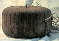
Fig. 1 Production I will try to give a method for making a transformer with only one device such as a tester, LATR, 220-volt incandescent lamps and a pair of mittens. The most important characteristic of a transformer is its overall power, which comes from the internal and external diameters of your core and the height, and in our case, the width of the plate. If you come across wide plates, you can cut them lengthwise with metal scissors from a plate 200 mm wide; it’s perfectly possible to make two 100 mm each. The most difficult thing, perhaps, is to form the first ring of your future transformer core in such a way that additional hands will be required to hold the plate rolled into a ring. Home You put on mittens and twist the first plate into a ring, after that, between the remaining tip of the plate and the rolled ring itself, you put the second plate into an overlay of about 50 mm and roll it onto the first one. As a result, you press the end of the first with the second plate and use this technology to roll all the other plates until you won't get something similar to a toroid like the one in Fig. 2.
Fig. 2 The core obtained in this way, in order to give it density between the plates, must be twisted inside (like twisting a photographic film into a tube) with the inner part of the core scrolling relative to the outer one. After two to three times, the density of your core will be sufficient and it will no longer spin inside. Secure the core with metal tape or better temporarily at 120 degrees with copper wire. Now let's take a ruler and measure the cross-section of the transformer core. If you are making RA on lamps like GU43B or GS35B, then roughly without calculations you can conclude that the cross-section of the transformer window should be within 60 square centimeters. The height of your core is determined by the width of your plate, the thickness of the set by the number of plates wound on. In this case, the height of the core is 10 cm, and the thickness of the set is 6 cm, while the outer diameter of the transformer core is 28 cm, and the inner diameter is 22 cm. To protect your network winding from mechanical damage at the corners, you need to cut out rings from cardboard, the internal and external diameters will be equal to your core with an allowance for wrapping at the corners. This is necessary to remove sharp edges resulting from cutting the plates lengthwise and at the corners when winding the wire. It is better to cut the rings out of electrical cardboard with a thickness of 1,0-1,5 mm, but you can place them in 2-3 layers from cardboard from shoe boxes, wrapping them at the corners, both outside the core and inside, 10 mm each with temporary additional fixation in several places with copper wire. Thus, you fix only one ring, so that at the bottom under the core it will resemble a small bath throughout the core. Why is this necessary:
To additionally fix the plates, you can use a ferrite mass made from low-frequency ferrite powder and varnish, but where can you get so much ferrite, so we only use varnish. Any varnish can be used, but only oil varnish or varnish used for electrical repairs. engines for our purposes, the PF283-4S varnish used for floors has proven itself well. Before pouring varnish into the slots of the core, it is necessary to heat the varnish to 40-60 degrees, and the core itself to about 80-100 degrees. Why is this necessary - when heated, the cracks of your core will increase to the maximum and there is no point in heating more, but a well-flowing varnish flows easily into all small cracks. All this is done until varnish appears on the opposite side of your core in the cardboard bath. After this, the process can be interrupted and the core can be allowed to cool to room temperature along with the poured varnish. After drying a little, the varnish will regain its viscosity and stop flowing through the core. All you have to do is add heated varnish while the core is cooling until it appears on top of the core and place a second ring of cardboard on top. Tighten the temporarily formed bag with copper wire, and after drying it can be removed. To protect the primary winding of your transformer, we will insert cardboard rings inside and outside along the entire perimeter. In factories, they use “tape tape” to insulate such transformers, but again it’s good if there is one, but if not. In place of the keeper tape, old sheets are used, which are torn lengthwise into strips 2-2,5 m long, depending on the length of the sheet and a width of 20-30 mm. Tape around the core with light tension to make 3-4 layers around the entire perimeter of the transformer core. After winding, all these layers must be saturated with varnish and left to dry. For those who do not believe that this impregnation will withstand 220 volts, you can also wrap varnished cloth 0,3-0,4 mm thick on top of the impregnated tape. The monolithic and well-plated core obtained in this way will serve you faithfully in your transformer. Coil To wind the primary winding, a wire of 0,8 to 1,5 mm is required, with an average diameter of 1,0 mm. If you have a wire with a diameter of 0,8-0,9 mm, then you will have to wind two windings with the same number of turns and the no-load current of your transformer connected to a 220-volt network. We will proceed from a conventional wire cross-section of 1,0 mm; this is necessary so that we can be guided that with a diameter of ~ 1,0 mm, the number of turns of the primary winding per volt tends to 1 turn/volt. All this is necessary in order to be able to safely wind 220-250 turns of wire for the network winding. If the wire diameter is less than 1,0 mm, then 250-300 turns. Now the crucial moment is to connect the first start-up of your transformer in series with the mains winding of the transformer in the LATR circuit with the motor previously set to 250 volts. Start reducing the voltage on the LATR to zero if you hear the hum of your transformer - this indicates that a small number of turns are wound in the network winding. It is necessary to reach such a limit when, with the LATR completely set to zero, your transformer does not hum and jumps from the high current in the network winding. Now you can take measurements with a tester, what did you get? How much current does your transformer draw? You need to be guided and strive to ensure that your transformer has an no-load current of about 100 mA and you have the opportunity to adjust the current after it is wound and installed in the circuit. For these purposes, 3-4 taps are wound up and made in increments of 50 turns from the already received no-load current of the transformer -100 mA. The insulation between the layers of the network winding can be anything that is available - this is thin and durable paper tracing paper, varnished cloth - 0,3 mm, just paper, even our “keep tape”. After receiving the no-load current of the transformer network winding at 100 mA and making a reserve on the taps, you can wrap the winding with “keep tape” for 3-4 layers and also impregnate it with varnish brand PF283-4S. Winding all other windings is exactly the same. Knowing the value of turns/volt in the network winding, you can calculate how many turns you need to wind to obtain the voltage you need in the other windings.
Fig. 3 A transformer for RA manufactured using this technology, with dimensions previously agreed upon, has the following data:
A garland of 10 220-volt incandescent lamps with a power of 300 watts each was used as a load. Data under long-term load for 2 hours of continuous operation with a wire with a diameter in the network and anode windings of 0,95 mm:
What more could a radio amateur want! Having made such a transformer, you can use it for any design. Using this technology, it can be done at any power. At the same time, there is always a lot of transformer iron in those places where such oil transformers are being repaired and it literally lies under your feet and rusts. At the same time, I immediately warn that everything needs to be calculated, the overall power and wire diameters are all that is required for calculations of this type of transformers, but the manufacturing conditions were agreed upon in advance for the case when there is only a tester, LATR is available in any school and incandescent lamps . All the best to you and long-term connections to you. Author: M. Gribak (UA9XEQ), mailto:ua9xeq@mail.ru; Publication: cxem.net
Artificial leather for touch emulation
15.04.2024 Petgugu Global cat litter
15.04.2024 The attractiveness of caring men
14.04.2024
▪ Realme Smart TV Stick FHD TV Keychain ▪ The Pilot headphones translate in real time ▪ New OMRON Sensor Detects Tilt Direction ▪ Video surveillance in the subway identifies the perpetrator
▪ section of the site Fundamentals of safe life (OBZhD). Article selection ▪ article to sink into oblivion. Popular expression ▪ article What is a vaccine? Detailed answer ▪ article cleaner. Job description ▪ article Fan on the video card. Encyclopedia of radio electronics and electrical engineering
Home page | Library | Articles | Website map | Site Reviews
www.diagram.com.ua |


 Leave your comment on this article: