|
|


 Arabic
 Bengali
 Chinese
 English
 French
 German
 Hebrew
 Hindi
Hindi Italian
 Japanese
 Korean
 Malay
Malay Polish
 Portuguese
 Spanish
 Turkish
 Ukrainian
 Vietnamese
|
ENCYCLOPEDIA OF RADIO ELECTRONICS AND ELECTRICAL ENGINEERING Transformerless voltage converter. Encyclopedia of radio electronics and electrical engineering
Encyclopedia of radio electronics and electrical engineering / Electronics in medicine In the January and February issues of the Radio magazine of the current year, it was told about the unique invention of our compatriot A.L. Chizhevsky - an air ionizer, later called the Chizhevsky Chandelier. Hundreds of readers call and write to the editorial office who are interested in this installation, which can create a relaxation area with mountain air in the apartment. Today's story is devoted to two more options for a high-voltage block needed to power an electro-fluvial chandelier-generator of negative air ions. As already reported in [1], the DC voltage of negative polarity supplied to the electro-fluvial chandelier should not be lower than 25 V, otherwise the desired effect from the air ionizer will not be. Therefore, any power supply assembled according to the schemes published in [000, 1] or designed independently must meet precisely this most important requirement.
A diagram of one of the variants of such a block is shown in Fig. 1. This is a voltage converter made on two powerful transistors VT1, VT2. They work in a generator assembled according to a push-pull scheme. The collector terminals of the transistors are connected to the I winding of the transformer, and the base terminals are connected to the II winding. The self-excitation of the generator occurs due to positive feedback between the collector and base circuits of the transistors. This process is also facilitated by the R1C2 chain, which determines the operating mode of the transistors. As a result of self-excitation of the generator, an alternating (more precisely, pulsed) voltage with a frequency of 3000 ... 4000 Hz appears at the terminals of the winding I. It is increased hundreds of times by the output winding III and is fed to a rectifier assembled according to the voltage multiplication circuit on high-voltage diodes VD5-VD10 and capacitors C3-C8. The rectified voltage of negative polarity is supplied to the chandelier through the limiting resistor R2. To power the generator, a rectifier was used, assembled on powerful diodes VD1-VD4 in a bridge circuit. The rectified voltage is filtered by capacitor C1. The alternating voltage to the rectifier is taken from the secondary winding of the step-down transformer T1. The primary winding of the transformer is connected to the network through the fuse FU1, switch SA1 and plug X1. Transformer T1 can be made independently on a magnetic core from transformer iron Sh20 with a set thickness of 30 mm. Winding I should contain 2200 turns of PEV-1 0,25 wire, winding II -120 turns of PEV-1 1,2. For a more accurate selection of the rectified voltage, it is desirable to make taps from the 90th, 100th, 110th turns. A ready-made transformer with a voltage on the secondary winding of 10 ... 12 V with a load current of up to 2 A is also suitable. Transformer T2 is made on a ferrite magnetic circuit from a television line transformer of the TVS series, consisting of two halves (1) - fig. 2.
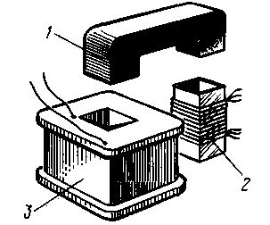
The high-voltage winding (3) is wound on a frame glued from textolite, fiberglass or organic glass 1 mm thick. Frame width - not less than 30 mm. The winding must contain 8000 turns of PELSHO 0,08-0,1 wire. In extreme cases, a PEV or PEL wire is suitable. Every 800 turns it is necessary to lay a layer of thin fluoroplastic tape or cover the winding with molten paraffin. It is necessary to strictly monitor that the turns of the upper layers do not fall on the lower ones. For the primary windings (2) you will need a sleeve, which can be glued from thick cardboard. Winding I should contain 14 turns of PEV-1 0,8 wire with a tap from the middle, and winding II - 6 turns of the same wire with a tap from the middle. It is advisable to cover the windings with paraffin and wrap with insulating tape. The halves of the magnetic circuit are inserted into the frame and the sleeve and pulled together (the old fastening of the line transformer is useful here). The generator transformer can also be wound on a magnetic core made of Sh20 transformer iron, the thickness of the set is 30 mm. In this option, a common frame is made of thick cardboard, getinaks or fiberglass. First, windings I and II are wound (respectively, 20 turns of PEV-1 1,2 and 16 turns of PEV-1 0,5 - both with a tap from the middle) and coated with paraffin. In addition, a layer of good insulating material is wound around them, for example, fluoroplastic tape 1 mm thick. Then winding III is wound - 7000 ... 8000 turns of PELSHO 0,1 wire. Here, too, every 800 turns, the winding is coated with paraffin. Oxide capacitors - any series, resistors - MLT. About options for high-voltage capacitors and diodes can be found in [1,2]. Bridge rectifier diodes can be replaced by others rated for a current of at least 2 A, for example, KD202. KD203. KD206, KD210, D242-D248 with any letter indices. In addition to those indicated in the diagram, KT816 transistors with any letter indices, KT818A-KT818V, and even any P216 (except P216G) are suitable. For transistors, it is necessary to make radiators with an area of 2 ... 2,5 cm60 from sheet aluminum or duralumin with a thickness of 100-2 mm.
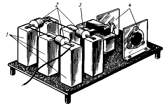
A possible mounting option for the device is shown in Fig. 3. High-voltage diodes D1008 (1), KOB capacitors (2), a home-made transformer (3) of the generator and transistors with radiators (4) indicated in the diagram are mounted on an insulating board (but not made of organic glass!) 2,5 mm thick, which is then placed in a housing made of insulating material (organic glass, textolite, plastic). Particular attention should be paid to the installation of diodes and capacitors. The connecting conductors between them should be short, and the soldering should be even and smooth. The sharp edges of the solder and the protruding ends of the conductors are carefully cleaned with a needle file to prevent the possibility of corona and the appearance of an ozone smell. A rectifier with a step-down transformer is assembled as a separate structure, but it is quite possible to place its parts on a common board with a generator. In this variant, it is advisable to install the SA1 switch near the mains socket. Checking the operation of the air ionizer begins with a rectifier. Instead of a generator, a resistor with a resistance of 1 ... 8 Ohms with a power of 10 W is connected as a load to its output (in parallel with capacitor C25) (a PEV resistor or home-made from a thick wire with high resistivity). Connect the X1 plug to the network and apply voltage through the SA1 switch to the T1 transformer. Measure the DC voltage across the load resistor - it must be at least 10 V. Next, connect the generator to the rectifier. If it is assembled correctly and the parts are in good order, a thin squeak of a high-voltage transformer will be heard. Otherwise, you need to swap the extreme terminals of the winding I or II, and possibly also select the resistor R1. If a sharp squeak or breakdown clicks appear, reduce the generator supply voltage - solder the rectifier to one of the transformer taps with a lower voltage. They make sure that there is no corona, for which they turn on the installation in the dark, look closely at the high-voltage part. If purple lights appear on the pins of the parts, this is a sign of corona. Soon you will smell the ozone. The installation is turned off, the places of soldering are inspected, if necessary, the sharp ends are cleaned and the corona leads are covered with molten paraffin. The final stage is high voltage control according to the method described in [1]. After that, the generator with a multiplier is installed near the chandelier and the output wire of the multiplier (the left output of the resistor R2 according to the diagram) is connected to the chandelier. The ground wire (from the lower output of the winding III of the transformer T2) is connected to the water supply or heating pipe. If the rectifier with transformer is mounted in a metal case, it is also grounded. A diagram of another version of the chandelier power supply is shown in fig. 4. According to the principle of operation, it differs little from that described in [1].
The mains voltage is rectified by the diode VD1. The rectified voltage is filtered by capacitor C1 and fed to the charging circuit R1C2. As soon as the voltage on the capacitor C2 reaches the ignition voltage of the thyratron VL1, it flashes. The capacitor is discharged through the primary winding of the transformer T1, the thyratron goes out, the capacitor starts charging again, etc. The high voltage pulses released on the secondary winding are fed to the already known voltage multiplier (it consists of eight stages in this version), and from its output to the chandelier. Rectifier diode - any, designed for a reverse voltage of at least 600 V and a current of at least 30 mA. Capacitor C1 - oxide, C2 - paper for the nominal voltage indicated in the diagram. Resistor R1 can be made up of three connected in parallel with a resistance of 47 kOhm. Transformer T1 - automotive ignition coil. Instead of a thyratron, you can turn on one or more dinistors of the KN102 series - by selecting the total voltage of their turn-on, it is easy to regulate the high voltage supplied to the chandelier. Literature 1. Ivanov B. "Chizhevsky's chandelier" - do it yourself. - Radio, 1997, No. 1, p. 36, 37. Author: B. Ivanov, Moscow; Publication: N. Bolshakov, rf.atnn.ru
Machine for thinning flowers in gardens
02.05.2024 Advanced Infrared Microscope
02.05.2024 Air trap for insects
01.05.2024
▪ section of the site Videotechnique. Article selection ▪ article Application of footages. video art ▪ article Why did Mark Twain choose such a pseudonym? Detailed answer ▪ article Features of the regulation of women's labor ▪ article Ultrasonic washing machine. Encyclopedia of radio electronics and electrical engineering ▪ article The simplest kind of pulling mechanics. Focus Secret
Home page | Library | Articles | Website map | Site Reviews
www.diagram.com.ua |


 Leave your comment on this article: