|
|


 Arabic
 Bengali
 Chinese
 English
 French
 German
 Hebrew
 Hindi
Hindi Italian
 Japanese
 Korean
 Malay
Malay Polish
 Portuguese
 Spanish
 Turkish
 Ukrainian
 Vietnamese
|
ENCYCLOPEDIA OF RADIO ELECTRONICS AND ELECTRICAL ENGINEERING Thermostabilizer for temperature 150...1000 °С. Encyclopedia of radio electronics and electrical engineering
Encyclopedia of radio electronics and electrical engineering / Power regulators, thermometers, heat stabilizers The circuit is designed to automatically maintain the desired temperature with high accuracy and can be used in various industrial and household devices to control the heating of a heat chamber or soldering iron. Main technical characteristics of the heat stabilizer 1. Operating temperature range +150...1000 °С. 2. The accuracy of maintaining the set temperature in the operating range is not worse than 2 °C. 3. The operating voltage of the heater can be from 100V to 400V. 4. Heater power is allowed up to 4 kW (or 8 kW when using a radiator for a triac with a larger area). 5. The temperature sensor is a Chromel-Alumel junction thermocouple. 6. The control circuit of the temperature stabilizer is electrically isolated by direct current from the power supply of the heater. 7. The heater circuit is switched on electronically without contact. 8. The power supply of the control circuit is carried out from a bipolar power supply with a voltage of 12V (the current consumption of the control circuit does not exceed 15 mA). It is permissible to connect up to 10 thermal stabilizer circuits to one power supply. The temperature stabilizer contains a minimum number of elements, which ensures high reliability, and small dimensions make it easy to place it inside any case. The device consists of two nodes: a control circuit and a power supply.
The control circuit (Fig. 1.17) is made on one dual microcircuit DA1 (140UD20A) and a symmetric thyristor (triac) VS1. On the DA1.1 element, a differential signal amplifier from a thermocouple is assembled, and on DA1.2, an integrator that controls the operation of a pulse generator on a unijunction transistor VT1. The pulses through the isolating transformer T1 are fed to the control of the switch VS1.
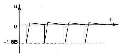
The use of an integrator in the circuit instead of the commonly used comparator makes it possible to provide a soft characteristic of the power change in the heater upon entering the thermal stabilization mode. This is done by changing the charge time of the capacitor C8, on which the frequency of the generator depends, and hence the initial opening angle of the triac. Until the voltage from the DA1 / 12 output exceeds the threshold value set by the resistors R1 and R2 (on DA1 / 6), the output of the DA1 / 10 microcircuit will be +12 V, which will ensure the operation of the generator (VT1) at maximum frequency. In this case, the shape of the pulses on the control electrode of the triac should have the form shown in Fig. 1.18. If the shape of the pulses is different, you should swap the conclusions on one of the windings of the transformer T1. The electrical circuit of the power supply unit of the temperature stabilizer can be assembled according to one of those shown in fig. 1.19 options. Both circuits have internal electronic overload protection and do not need special explanations, as they are typical. When using one power supply for several thermostats, each control circuit is switched on by a separate toggle switch.
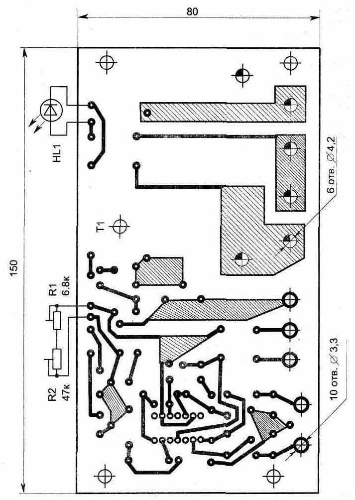
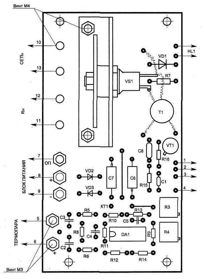
The topologies of printed circuit boards and the location of parts are shown in fig. 1.20...1.22. The triac is mounted on a radiator consisting of two copper plates, one of which is shown in fig. 1.23. For the convenience of connecting the external circuits of the circuit, M1.21 and M4 screws with nuts are fixed on the board (Fig. XNUMX).
The circuit uses a precision microcircuit, and replacing it with another type is unacceptable, since this will worsen the accuracy of maintaining the temperature due to an increase in zero drift, which will be commensurate with the signal from the thermocouple. The pulse transformer T1 is wound with PELSHO-0,18 wire on an M4000NM1 ferrite ring of size K16x10x4 mm or an M2000NM1 - K20x12x6 mm ring and contains 1 - 80 turns, 2-60 turns in the winding. Before winding, the sharp edges of the core must be rounded with a needle file. Otherwise they will cut the wire. After winding and impregnating the coil with varnish, it is necessary to make sure that there is no leakage between the windings, as well as the windings and the frame ferrite. The remaining details of the circuit are not critical and can be of any type, for example: variable resistors R1 and R2 of the SPZ-4a type; R3 and R4 - tuned multi-turn SP5-2; fixed resistors type C2-23; electrolytic capacitors C6 and C7 - K53-1A for 16 V; the rest are of the K10-17 type. Diodes VD2, VD3 are designed to protect the circuit from improper connection of the power source and can be any, for current up to 100 mA. When connecting the control circuit, it is necessary to observe the phase position indicated in the figure (if the connection is correct, the mains voltage phase must be on the triac radiator). This is especially important if several thermostats are connected from one power source. When power is applied to the control circuit, the heating of the RH load should turn on. The indicator of turning on the heater is the glow of the HL1 LED or a lamp connected in parallel with the load.
To set the stabilization temperature, set the regulators R1, R2 to the middle position and,
When the process of thermal stabilization is established, you can adjust the temperature with the regulator EXACTLY. The circuit allows you to have several fixed temperatures when switching S1. In this case, the desired temperature is adjusted by the corresponding trimming resistors R3 and R4 on the control board. Publication: cxem.net
Machine for thinning flowers in gardens
02.05.2024 Advanced Infrared Microscope
02.05.2024 Air trap for insects
01.05.2024
▪ Wearable Personal Cinema Sony Wireless Neckband Speaker ▪ Low temperature record for quantum devices
▪ section of the site House, household plots, hobbies. Article selection ▪ article Great combinator. Popular expression ▪ article What is an antibody? Detailed answer ▪ article winding machine operator. Standard instruction on labor protection ▪ article Improved ignition unit. Encyclopedia of radio electronics and electrical engineering
Home page | Library | Articles | Website map | Site Reviews
www.diagram.com.ua |


 Leave your comment on this article: