|
|


 Arabic
 Bengali
 Chinese
 English
 French
 German
 Hebrew
 Hindi
Hindi Italian
 Japanese
 Korean
 Malay
Malay Polish
 Portuguese
 Spanish
 Turkish
 Ukrainian
 Vietnamese
|
ENCYCLOPEDIA OF RADIO ELECTRONICS AND ELECTRICAL ENGINEERING Clock with thermometer and barometer. Encyclopedia of radio electronics and electrical engineering
Encyclopedia of radio electronics and electrical engineering / Clocks, timers, relays, load switches The proposed device is built on the AT90LS8535 microcontroller, it shows not only time, but also temperature, as well as atmospheric pressure, thus replacing three conventional household appliances. It can be connected via a serial interface to a personal computer, which will help calibrate the scales of the thermometer and barometer, and, if necessary, collect data to display graphs of their readings for a selected time interval. On the LED indicator of the device, you can observe the current time values in the form e HH.MM; temperature at the place where the remote sensor is installed, °С; atmospheric pressure, mm Hg. Art. A three-level ('normal - attention - discharged') indication of the backup battery status is provided. ..50 mm Hg with an error of 50...0,1 mm Hg. Structurally, the device consists of three modules (boards) - a controller, indication and power supply, placed in a case measuring 210x160x80 mm with a transparent window for indicators, and an external temperature sensor connected to the main unit with a three-wire cable up to 20 m long. The atmospheric pressure sensor is located inside the case . The choice of the Atmel AT90LS8535 microcontroller was due to the following circumstances:
The AT90LS8535 microcontroller can be replaced with a more modern ATmega8535L or common ATmega10Z, ATMega603 of the same company without changing the program. However, the last two microcircuits are much more expensive and are produced only in a plenary 64-pin package, which will require a significant complication of the printed circuit board. CONTROLLER MODULE In the controller module, the diagram of which is shown in Fig. 1, the main components of the device are located: microcontroller DD2; converting UART signals of the microcontroller to standard levels of the RS-232 interface (DD1 chip); unit for converting the resistance of the temperature sensor RK1 into voltage (DAI, DA2 microcircuits, transistors VT1, VT2); pressure sensor (BP1); control keys for LED indicators (transistors VT3-VT30); RS-232 interface plugs (XP1), microcontroller programming (XP2) and for connecting indicators (XP3).
Under the control of the microcontroller DD2, the keys on transistors VT3-VT12, VT21-VT30 are connected in turn to the power supply of the common anode circuit of ten seven-segment indicators, their cathodes switch transistors VT13-VT19. The VT30 transistor controls a pair of LEDs located between the hour and minute digits of the indicator. From pin 29 (PC7) of the microcontroller, a signal is sent to the temperature minus sign LED, and from pins 6 (PB5) and 7 (PB6) - to a two-color LED indicating the status of the backup battery. All indicators mentioned above are located outside the controller module. Since pins 6, 7 of the DD2 microcircuit are used and for its programming it is desirable to carry out this operation by disconnecting the cable connecting the controller and display modules from the HRS plug. Voltages proportional to the measured values are supplied to three outputs of the DD2 microcontroller, programmed as inputs of three of the eight available channels of the built-in ADC. Output 40 (PA0 / ADC0) temperature, 39 (PA1 / ADC1) - pressure, 38 (PA2 / ADC2) - battery voltage. The exemplary for the ADC is the voltage +32 V A applied to pin 5 (AREF) of the microcontroller, which significantly reduces the requirements for the stability of the latter. The fact is that the output voltage of temperature and pressure sensors is proportional not only to the measured parameters, but also to the supply voltage. Changing the reference voltage along with it eliminates this dependence in the output code of the ADC. Although deviations of the reference voltage from the nominal value introduce an additional error in the result of measuring the battery voltage, in this case this is not so important. The thermistor RK1 - temperature sensor - is the winding of the RES60 relay (passport RS4.569. 435-00) with a resistance of 1900 + 120 / -380 Ohm at 20 ° C. Other copper windings of approximately the same resistance can be used here, including the windings of the RES49 relay (passport RS4.569.421-00), RES79 versions DLT4.555.011. DLT4.555.011-05. The resistance of the copper wire of the winding depends linearly on temperature and is quite stable over time. If its value is known at temperature T0 (for example, at 20 °C), then at temperature T the resistance becomes equal to R(T) = R(T0)[1 +0,004(T T0)]. The design of the sensor can be similar to that shown in Fig. 2.
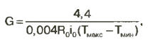
Stranded insulated connecting wires 1 (for example, MGTF) are soldered to the terminals A and B of the relay 4, passing them through the holder tube 2 filled with epoxy resin 3. To prevent leakage of the liquid resin, the places where the tube 2 is loosely attached to the relay 1 are sealed, for example, with plasticine , which is easy to remove after polymerization of the resin. Before pouring, it is necessary to put a flexible PVC tube 5 on the twisted wire harness. It will protect not only from adverse weather conditions, but also from wire breaks during frequent kinks, especially at the point of exit from the tube 2. Do not bend the relay terminals or cut off unused ones. This can damage their glass insulators, and moisture that has penetrated inside the hermetic case of the relay will cause corrosion, and over time, a break in the ultra-thin winding wire. On the op-amp DA1.1, DA1.2 and field-effect transistors VT1, VT2, two 1 mA current stabilizers are assembled. Their identity is ensured by applying an exemplary voltage from a common divider R1R2 and the equality of the resistances of the feedback resistors R3 and R4. The current of the upper stabilizer according to the circuit flows through the RK1 sensor and two connecting wires connected to pins 1 and 3 of connector X1, the lower current flows through the exemplary resistance (resistor R5) and also two wires connected to pins 2 and 3. Since the result of the measurement is the voltage difference at the sources of transistors VT1 and VT2 equal voltage drops on the wires and connector contacts cancel each other out when subtracted. The value of the resistor R5 is slightly less than the resistance of the sensor RK1 at the minimum measured temperature, therefore, it corresponds to an almost zero output signal of the converter. If a sensor with a resistance significantly different from 1850 Ohm at room temperature is used, it is necessary to calculate its resistance using the above formula at the temperature of the lower boundary of the measurement interval (for example, -50 ° C) and take the nearest lower value from the E5 series as the value of R24. According to this series they produce resistors with a tolerance of no more than ± 5%, however, you need to use a precision one, for example, C2-29V with a tolerance of + 1% or less, only such a resistor will ensure the minimum effect of temperature changes at the installation site of the device on its readings. The subtraction operation is performed by a precision DC differential amplifier on the op-amp DA2.1, DA2.2. The operation of such an amplifier is described in [3]. The exact equality of the resistances of the resistors R8-R11 is necessary, therefore they should be selected with tolerances of no more than ± 0,1 ... ± 0,25%, resistors R3, R4 should also have similar tolerances. The gain of the differential amplifier is set so that the maximum possible output voltage for the op-amp, approximately 4,4 V, corresponds to the upper limit of temperature measurement. The required value of the gain is found by the formula
where R0 is the resistance of the sensor at room temperature, kOhm; i0=1 mA - rated current through the sensor and reference resistor; Tmax, Tmin - respectively, the upper and lower limits of the measurement interval, °C. Given the equal values of the resistors R8-R11 (they can be chosen by any from 2 to 10 kOhm), the value of the resistor R6 is calculated by the formula
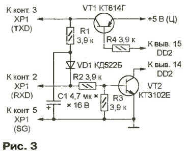
The requirements for the accuracy of the value of this resistor are not very high, the errors can be compensated by software. But like other resistors of the measuring unit, it must be thermally stable. The pressure sensor BP1 - MPX4115AP is manufactured by Motorola specifically for electronic barometers and barometric altimeters. In the range of 0,15 ... 1,15 kPa (112,5 ... 862,5 mm Hg), the dependence of its output voltage on pressure is linear with a normalized slope. However, the zero offset of the characteristics of different sensor instances reaches 20 mm Hg. Art. Offset compensation in this device is assigned to the microcontroller program. The first output of the sensor is easy to identify by the semicircular cutout on it. If the barometer readings in the manufactured device are unstable, the interference induced on the output circuit of the BP1 sensor is most often to blame. To get rid of them, it is enough to install a capacitor with a capacity of at least 1 uF between terminals 2 and 0,047 of the sensor, which is not shown in the diagram. The R7C11 circuit provides a reliable installation of the DD2 microcontroller in its initial state when the power is turned on. Capacitors C1-C10, C12 - blocking, C13 and C14 are necessary to excite the quartz resonator ZQ1. The printed circuit board of the controller module is double-sided made of foil fiberglass 1,5 mm thick. Its dimensions are 190x120 mm with a 90x60 mm cutout. A feature of the circuit and design of the module is three independent "common" wires for analog, digital circuits and indicators. In the assembled device, these wires are connected to each other only in the power module. This reception reduces the interference created by analog nodes, digital and display module. When testing and setting up a controller powered by "non-standard", for example, laboratory sources, do not forget to connect the common wires of the latter to each other. Resistors R1-R6, R8-R11 - C2-29V or other precision resistors with the tolerances indicated above. The rest of the resistors are ordinary MLTs or C4-1. All capacitors are any ceramic. Quartz resonator ZQ1 - NS-49 or another for the desired frequency. Plugs ХР1-ХРЗ - two-row pin blocks PLD. The block part of the PC4 connector (X1) is installed on the instrument case. Its contacts are connected to the corresponding pads of the printed circuit board. The RS-232 interface signal level converter MAX202CPE (DD1) can be replaced by one of its many functional analogues, which differ only in the number of conversion channels, the recommended ratings of capacitors C4, C5, C9, C10 and the level of protection of inputs and outputs from interference and overvoltage. In extreme cases, the DD1 chip can be replaced with a node on two transistors according to the circuit shown in Fig. 3. The negative voltage necessary to form a full-fledged TXD signal in this case is obtained by rectifying the RXD signal from the computer using the VD1C1 circuit. Transformerless converters are built into specialized interface microcircuits to obtain increased positive and negative voltage.
Dual precision op amps MAX478СРА (DA1, DA2) will be replaced by quad MAX479CPD. Similar op amps are manufactured by Analog Devices (AD8512, AD8513). In extreme cases, single domestic KR140UD26A will do. Field-effect transistors KPZ0ZE can be replaced with KP302 with letter indices B-G or others with an n-channel and an initial drain current of at least 3 ... 5 mA. Instead of KT315G transistors, you can install KT315B or on KT3102 with any letter indices, instead of KT972A - KT817G, and instead of KT973A - KT973B. Of course, it is permissible to use any other transistors of approximately the same power with n21E of at least 100, including imported ones. INDICATION MODULE The purpose of this module is clear from the name, and the circuit is shown in Fig. 4. Between the seven-segment LED indicators of hours (HG1, HG2) and minutes (HG3, HG4) with digits 25 mm high, there are LEDs HL3 and HL4, flashing at a frequency of 0,5 Hz. The remaining indicators are half the size. HG5-HG7 show the temperature, HG8 and HG9 - the unit of measurement (°C). Thanks to the resistor R2, the decimal point lights up between the digits of units and tenths of a degree. The controller displays the value of atmospheric pressure on the HG10-HG12 indicators, the unit of measurement of which (mm) is visible on the HG13 dual sixteen-segment indicator. Please note that the controller does not control the indicators HG8, HG9, HG13. The necessary symbols are "programmed" by connecting the cathodes of the segments of these indicators to a common wire through resistors R4-R16. To the left of the HG5 indicator (a digit of tens of degrees), a flat LED HL1 is horizontally located - a minus sign. Bicolor LED HL2 is used to indicate the status of the backup battery. While the voltage is normal, it is green, a periodic change in the color of the glow signals that it is time to replace the battery. If the color is solid red, the battery is either dead or missing. The printed circuit board of the module is double-sided made of foil fiberglass with a thickness of 1,5 mm. Its dimensions are 190x75 mm. The XP1 plug (PLD-24, identical to the XP1 controller plug) and all resistors are mounted on one side of the board. Indicators HG13 - HG1 and LEDs HL4-HLXNUMX - on the opposite side, having previously painted its surface and soldering points of the plug pins and resistor leads with dark paint. This enhances the appearance of the instrument by creating a dark background for the indicators and hiding device details from the user. The diagram (see Fig. 4) shows the types of LEDs and indicators manufactured by Kingbright, but similar ones from other companies, including domestic ones, can be used with equal success.
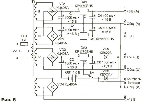
Indicators HG1-HG4 -yellow, HG5-HG7 - green, the rest - red glow. Of course, you can choose other colors according to your own taste. The color of the HL1 LED should be the same as that of the HG5-HG7 indicators, and the HL3, HL4 LEDs should be the same as the HG1-HG4 indicators. It is desirable to use LEDs with diffuse light scattering (with a matte lens). To eliminate unnecessary illumination of the design elements of the device, cover the side surfaces of the HL1 and HL2 LEDs with some opaque paint. POWER MODULE On fig. 5 shows a diagram of a module that generates four voltages: + 5 V (A) and -5 V - to power the analog components of the device; +5 V (C) - for its digital nodes; pulsating (unfiltered) voltage +12 V - for indicators. The voltages from the corresponding windings of the transformer T1, after being rectified by diode bridges VD1 - VD4, are supplied (except for +12 V) to the filter capacitors C1-C3 and integral stabilizers DA1-DA3. The module has three outputs of the common wire: Common. (A) - "analogue"; Tot. (C) - "digital"; Tot. (I) - for indicators. They are interconnected only at one point on the power supply module board, and in all other modules they are not electrically connected. This is necessary to reduce the level of interference generated by the digital nodes of the analog controller module.
Transformer T1 - TP112-19 with an annular magnetic core, on which, in addition to the existing windings I-III, two more are wound: IV (80 turns of PEV-2 wire 0,2 mm) and V (120 turns of PEV-2 wire 0,5 mm ). You can use any other transformer with an overall power of at least 15 W with the required number of secondary windings (I-IV - 7 ... 9 V / 0,05 A each; V - 12 ... 15V / 0.5 A). The voltage of the backup galvanic battery GB1 through the switch SA1 and the diode VD6 is supplied to the +5 V (C) output if there is no corresponding voltage at the output of the stabilizer DA3. This supports the operation of the controller when the device is disconnected from the network, which is necessary not only to protect against failures in the event of a network failure, but also, for example, to carry the device from one room to another. The GB1 battery is made up of three AA batteries connected in series. Most of the time, the current drawn from the battery is negligible, so it is best to use alkaline (alkaline) electrolyte cells, which are characterized by a minimum self-discharge and a maximum allowable shelf life. The most reliable are "branded" elements of well-known manufacturers. They can last several years without replacement, and cheap fakes sometimes turn out to be inoperative after a few weeks. Switch SA1 is connected to a common wire voltage control circuit of the battery GB1 in the absence of the latter. This eliminates false indicator readings. The printed circuit board of the power module is single-sided with several wire jumpers. Board dimensions - 120x100 mm. Integrated stabilizers DA1 and DA3 can be replaced with any domestic or imported ones for a positive voltage of 5 V (KR1158EN5, 78L05, LM2931AZ-5.0), DA2 - for the same negative (79L05, LM2990T-5.0). Oxide capacitors - K50-35 or their imported counterparts. Diodes VD5, VD6 - any low-power. If possible, install Schottky or germanium diodes here. True, a rather large reverse current of the latter can adversely affect the life of the GB1 battery. MICROCONTROLLER PROGRAM The source code of the program is written in AVR-assembler. The contents of the hex-file obtained as a result of the translation of the program are shown in Table. 1. It is he who needs to be loaded into the program memory of the DD2 microcontroller.
The operation of the program after turning on the power begins with the initialization of the microcontroller - setting the operating modes of the timers, the interrupt system, I / O ports, UART, as well as writing the initial values \uXNUMXb\uXNUMXbof variables to the registers and memory cells. After that, an endless loop of waiting for receiving commands via the serial interface is launched. Every second interrupts from timer 1 count time. On interrupts from timer 0, the procedure for dynamic control of the output of information to the LED indicators works, and the results of the ADC are read. The interrupt period from the timer is 0 - 0,5 ms, so the information in all ten bits of the indicator is updated every 5 ms. The next ADC count is obtained when processing each 32nd interrupt from timer 0. 1024 counts of one of the parameters (temperature, pressure or voltage) obtained in 64 ms are added, then the sum is divided by 64, and the resulting average value is stored in RAM for further calculations. For the next 1024 ms, the ADC measures another parameter. Thus, the full cycle of polling the sensors is a little more than 3 s. After that, the microcontroller performs the procedures for calculating the physical values of the measured quantities and prepares them for output to the indicator. The microcontroller calculates the number X displayed on the indicator according to the formula X=K(NZ), and the coefficients K and Z when calculating temperature and pressure are different. Their values are "protected" in the program code and are transferred from it to the RAM during initialization. If necessary, the coefficients can be "adjusted" to the real characteristics of the sensors using a computer connected to the instrument. The new values are valid until the microcontroller power is turned off; they are not saved in the non-volatile memory. The microcontroller monitors the state of the battery by comparing the result of measuring its voltage with two thresholds set in the program. When the battery voltage is more than 3,3 V, the levels at the outputs PB5 and PC7 of the microcontroller are such that the color of the HL2 LED (see Fig. 4) is green. If the battery voltage is in the range of 1,25 ... 3,3 V, the polarity of the voltage applied to the LED and the color of its glow change every second. With a voltage drop below 1,25 V, the LED is permanently red. The given threshold values are approximate, as they depend, for example, on the supply voltage +5 V (A). The low power modes (Idle, Power Down and Power Save) provided in the AT90LS8535 microcontroller are not used by the program even when running on a backup battery. Its energy is already enough to power the hours disconnected from the network for several days. Reception via the RS-232 interface and the execution of six commands are provided, given in Table. 2.
The computer, with the COM port of which the device is connected by a null-modem cable, sends commands by transmitting one to three bytes indicated in the table and receives responses to them in the following mode: exchange rate - 9600 Baud, number of data bits - 8, number of stop bits - 1, parity is disabled. In table. 3 shows the addresses where various variables and parameters are stored in the RAM of the microcontroller. Only the lower bytes of the addresses are given, which are indicated in the commands according to Table. 2. High byte 01H is implied.
EXTERNAL COMPUTER PROGRAM The Lclock program, intended for clock control, thermometer and barometer calibration, was prepared using the Delphi package version 3.0, the Windows application development system from Borland. To access computer COM ports, the library of corresponding functions from SaxSoft (file comm.fnc) was used. The COM1 port connector (by default, the Lclock program menu allows you to use the COM2 port if necessary) is connected with a null-modem cable to the corresponding clock connector. The view of the main program window is shown in fig. 6. Every 3 s, it reads the current values of time, temperature, pressure from the watch controller memory, displaying the values that duplicate the readings of the LED indicators in the corresponding screen windows. In addition, the program reads and displays the backup battery voltage.
When the "Record-On" mode is enabled, the received data is automatically saved in the disk file sclock.ini. They can be used to calculate the average values of temperature and pressure for a certain period, plotting their changes and other similar operations. The default mode is "Record-Off" and no recording is made. If, at the time of enabling the recording, the program found that the sclock.ini file already exists, it supplements the data in it with new ones, otherwise it creates a new file with the same name. The Lclock program also reads and displays the values of all coefficients used by the microcontroller in calculating the coefficients. They can be modified manually by entering the required values in the appropriate windows, or automatically by performing one of the calibration procedures ("Automatic Calc"). It also provides for setting the current time ("Set time") and adjusting the frequency division ratio of the clock generator of the microcontroller ("Set speed") to adjust the clock. To set the exact time, it is enough to set new values of minutes and hours in the corresponding windows or click the "Set from computers" button. In the latter case, readings corresponding to the computer's system time will be set. This, in turn, can be accurately set via the Internet using atomic clocks (see ., for example, [4]).The "Reset sec" and "Set sec=59" buttons are used for precise clock synchronization. They set the value of seconds not displayed on the indicators and the screen to 0 or 59, respectively. THERMOMETER AND BAROMETER CALIBRATION The measurement errors given at the beginning of the article characterize the potential capabilities of the device hardware. Actual errors in temperature and pressure measurements largely depend on the accuracy and accuracy of the calibration. In the process of performing this operation, the exact values of the coefficients used to convert the dimensionless numbers read from the ADC registers into the values of physical quantities in the appropriate units are determined and recorded in the device memory. For each of the quantities - temperature T and pressure P - two parameters are required: zero offset (ZT, ZP) and slope (Kt, KP) of the characteristic. As you know, the microcontroller performs arithmetic operations only on integers, and the parameters Km, KR, as a rule, are fractional. Therefore, the program actually works with their values multiplied by 1024. They are stored in the RAM cells of the microcontroller and displayed in the windows of the Lclock program. The final result of the temperature or pressure calculation is obtained by scaling - dividing the preliminary result by 1024 Two calibration points are enough to calculate the parameters. The closer to the edges of the most commonly used temperature or pressure range they are, the better. To calibrate, for example, a thermometer, its readings before calibration (T1, T2) and the readings of a reference thermometer (T01, T02) must be known at the selected points. Then the new values of Kt and Zt are calculated by the formulas (Who and Zto are the old values of the parameters):
As a reference for calibration, a mercury aquarium thermometer, which can be purchased at a pet store, is best suited. The error of household alcohol thermometers is too large. Having launched the Lclock program, the temperature sensor and the reference thermometer are dipped into hot water (it must be continuously stirred). After keeping them there for at least 5 minutes to stabilize the readings, press the "Temperature-Automatic Calc-Calc & Set" button in the corresponding program window, enter the value read from the scale of the reference thermometer into the "First Point" window and press the Enter key. At this moment, the program will automatically record the readings of the temperature sensor. The sensor and thermometer are transferred to cold water with a temperature that differs from the previous one by 20 or more degrees Celsius. After the readings stabilize and enter them into the "Second Point" window, the new values of the Kt and ZT coefficients will be calculated and written to the instrument's RAM. The barometer is calibrated in a similar way. The formulas for calculating KP and ZP are similar to those given above for Kt and ZT. Naturally, the temperature values T in them are replaced by pressure values P. However, calibration is difficult because instruments for accurately measuring atmospheric pressure are available only in professionally equipped laboratories. Therefore, it is necessary to use Internet data as exemplary data (for example, , , ), radio and television meteorological services. Unfortunately, they are inaccurate, and correct them belatedly. Therefore, without limiting the information of any one service, you need to look at the messages of several, discarding obvious errors and averaging plausible values. Before launching the Lclock program to calibrate the barometer, wait until the pressure becomes sufficiently low or, conversely, high (extreme values in the Moscow region are 720 and 770 mmHg). Enter the true pressure in the "First Point" window by first pressing the "Pressure-Automatic Calc-Calc&Set" button. This value will be written to the disk file along with the pressure sensor readings. Now the program can be closed and before the atmospheric pressure approaches the opposite extreme value, turn off the computer. When restarting the Lclock program, press the "Pressure-Automatic Calc-Calc&Set" button again and enter the actual pressure value in the "Second Point" window. After that, the corrected parameters КР and ZP will be automatically calculated and written to the RAM of the device, and the program will read the data on the first calibration point from the file. The calibration results are stored by the watch controller in RAM, so if the power supply is completely disconnected (for example, when replacing or failing the backup battery), they will be lost. To avoid this, it is recommended to press the "Save as defaults" button after the calibration, and the set values of the coefficients (as well as the frequency division factor of the quartz) will be stored in the disk file. To restore the lost values, it will be enough to press the "Set default coeff." button. write down the found values on paper, and, if necessary, enter them into the appropriate windows. If the sensors are not expected to be replaced during operation, you can force the controller to accept the results of a default parameter calibration once performed. The most correct way to do this is to change the corresponding constants in the assembler code of the program, compile it and reprogram the microcontroller. Without resorting to intervention in the source text, the same operation can be performed by simply changing some bytes directly in the hex file (see Table 1). On fig. 7 shows how the values of the parameters KP, ZP, Kt, ZT are recorded in it. The division factor of the clock frequency of the microcontroller, necessary for the accurate running of the clock, is also recorded there. Its value must be numerically equal to 1/64 of the clock frequency of the DD2 microcontroller in hertz. In practice, the deviation of this frequency from the value indicated on the ZQ1 quartz resonator (4096 kHz) can reach hundreds of hertz.
In each changed line of the hex file, the last byte, the checksum, must be corrected. On fig. 7 these bytes are underlined. Arithmetically adding the values of all but the last bytes of the string, subtract their sum from the nearest higher power of 2. The low byte of the resulting difference will be the new checksum. Literature
Author: Yu.Revich, Moscow
Machine for thinning flowers in gardens
02.05.2024 Advanced Infrared Microscope
02.05.2024 Air trap for insects
01.05.2024
▪ Integration of smoke detectors into computers and mobile devices ▪ New digital camera reference design announced ▪ Atomic clocks will become even more accurate ▪ Ford Mustang Lithium Electric Muscle Car
▪ section of the site Electrician in the house. Article selection ▪ article Winged words. Popular expression ▪ article Where does a shark live after a vegetarian diet? Detailed answer ▪ dryer article. Standard instruction on labor protection ▪ article Transmitter for telecontrol. Encyclopedia of radio electronics and electrical engineering
Home page | Library | Articles | Website map | Site Reviews
www.diagram.com.ua |


 Leave your comment on this article: