|
|


 Arabic
 Bengali
 Chinese
 English
 French
 German
 Hebrew
 Hindi
Hindi Italian
 Japanese
 Korean
 Malay
Malay Polish
 Portuguese
 Spanish
 Turkish
 Ukrainian
 Vietnamese
|
ENCYCLOPEDIA OF RADIO ELECTRONICS AND ELECTRICAL ENGINEERING Economic security sensor. Encyclopedia of radio electronics and electrical engineering
Encyclopedia of radio electronics and electrical engineering / Safety and security The most important characteristic of the security system is its power consumption in standby mode. A schematic diagram of an economical security sensor that generates an alarm when a controlled object (CP) is touched is shown in fig. 1. A controlled object can be, for example, a door lock.
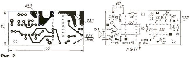
The alternating voltage generator, to which the sensor will respond, is a C6C7 capacitive divider connected to the AC network. The voltage at the input of the threshold device (element DD1.1) depends on the current that occurs in the circuit C6C7R10R2C1R1Ckp, where Cp is the capacitance connected to the KP. Resistor R1 and capacitor C1 attenuate high-frequency interference. In standby mode, the self-capacity of the gearbox is small. In this case, the current through R1 must be so small that the voltage at the input of element DD1.1 is less than the switching threshold. When you touch the KP, its capacitance will increase and the current will increase. If it reaches a value at which the voltage at the DD1.1 input exceeds the switching threshold, then a sequence of rectangular pulses will appear at the output of the DD1.1 element, following at a frequency of 50 Hz. The counter DD2, counting the declines of these pulses, will generate at its output 28 (output of the 9th digit) after 5,12 s a high-level signal that will turn on the piezo siren HA1. The device contains an infra-low-frequency generator (elements DD1.2-DD1.4), at the output of which there are pulses with a duration of 2 ms with a repetition period of 10 s. These pulses are fed to the input R of the counter DD2 and periodically return it to its original zero state. Therefore, the duration of the sensor alarm will not exceed 5 s in any case. But if touching the control panel continues, the alarms will be repeated. The chosen time of 5 s should be enough for the owner, who habitually quickly unlocks his door with a key, and is unlikely to be enough for someone who comes with a master key. Of course, this time can be changed by switching the resistor R7 to another output of the counter DD2. The high efficiency of the sensor in standby mode is ensured by the resistor R6, which lowers the supply voltage of the microcircuits to 3,5 ... 4 V. Only with such a power supply, the current consumed by the device (mainly the through current of the transient mode in the infra-low-frequency generator) decreases to 15 μA. The printed circuit board of the device is made of fiberglass with a thickness of 1,5 mm foiled on both sides (Fig. 2).
The foil under the parts serves only as a common wire for the sensor - connections to it with the leads of capacitors, resistors, etc. are shown as blackened squares. Conclusions 7 DD1 and 8 DD2 are bent to the side before installation. The squares with a bright dot in the center show the position of the jumpers that pierce the board and connect the negative terminals of capacitors C4 and C5 to the common wire foil. In places where conductors pass through the foil, protective circles with a diameter of 1,5 ... 2 mm should be etched. Transistor VT2 is mounted above the DD2 chip, before that, its conclusions should be bent. Almost all resistors in the device are MLT-0,125 (R4 - KIM-0,125). Capacitors C1 - KM-6, C2 - K10-176, C3 - KM-5, C4 and C5 - any oxide of suitable sizes. Capacitors C6 and C7 of the K15-5-H70-1.6 kV type are installed in a standard or specially made mains plug, which is connected to the board with a flexible mounting wire of the required length. The sensor has a high sensitivity and therefore the intrinsic capacitance of the BC cannot be too large. Otherwise, the sensor will operate from its own capacitance and its sensitivity will need to be reduced. This can be done by using a smaller resistor R2 and (or) a larger capacitor C1. A slight decrease in the sensitivity of the sensor (2...3 times) can be achieved by connecting its input to the CP through a small capacitor (10...50 pF). Although the large intrinsic capacitance of the CP will in any case reduce the useful signal. The sensor is installed near the controlled object. The length of the conductor going to the CP should not exceed 30...50 cm. The power source can be any 6-volt battery capable of supplying the current consumed by the siren. Almost any of the nominally 12-volt piezo sirens can work in the sensor: almost all of them retain sufficient acoustic power with a significant decrease in the supply voltage. The AC-10 siren sounds quite loud even with a 6-volt power supply, the current it consumes in this mode is 80 ... 90 mA. With a standby current of 15 μA, the service life of the supply battery will be determined by its self-discharge. Powering the sensor, equipped with a 1400 mAh lithium battery, can be left unattended for several years. For example, batteries DL223A (dimensions - 19,5x39x36 mm) and DL245 (17x45x34 mm) have such a capacity. The reader may have a question, since for the normal operation of the sensor you need a 50-Hz signal from the mains, why not power the sensor itself from it? Because, first of all, the security system should not depend on the power supply of the protected object, which can be removed in order to deactivate its protection. When the mains is turned off, the signal level at the output of the capacitive sensor divider will decrease, but not to zero. Even with its two-wire disconnection (and the switch often breaks only one wire), the amplitude of pickups along parallel wires may be quite sufficient for a sensor with its high input impedance. Although, of course, nothing prevents us from making an automatically turning on autonomous generator for such a case (it is inserted into the gap of the wire coming from the capacitive divider). And in conclusion - about the "guided" 50-Hz sensors. It would seem that there is no need for any special contact of the sensor with the mains: just touch the input of the ultrasonic frequency converter so that a pickup signal appears at its output. But such sensors, which work so well on the lab bench, when powered by batteries and placed where they are needed, are extremely unstable, and more often they don't work at all. The reason is simple - on a laboratory table, when the sensor is connected to a mains (!) power supply, it is connected to the mains through the interwinding capacitance of the mains transformer, and there is no such connection with autonomous power supply. In the described design, this connection is introduced explicitly - through a capacitive divider. Resistors R1 and P10 must be rated for at least 0,25 watts. This is necessary in order to avoid electrical breakdown along the surface of the resistors. Author: Yu.Vinogradov, Moscow
Machine for thinning flowers in gardens
02.05.2024 Advanced Infrared Microscope
02.05.2024 Air trap for insects
01.05.2024
▪ Moonshine instead of gasoline ▪ MSP430FR6047 - microcontroller for ultrasonic meters ▪ Restoring vision with wireless implants ▪ Mushrooms found to secrete gold
▪ section of the site Electronic directories. Article selection ▪ article How drunk Zyuzya. Popular expression ▪ Who Discovered Insulin? Detailed answer ▪ article Courier knot. Travel Tips ▪ article Water pump control device. Encyclopedia of radio electronics and electrical engineering ▪ article Ring of the fakir. Focus Secret
Home page | Library | Articles | Website map | Site Reviews
www.diagram.com.ua |


 Leave your comment on this article: