|
|
ENCYCLOPEDIA OF RADIO ELECTRONICS AND ELECTRICAL ENGINEERING Multichannel security and alarm devices. Encyclopedia of radio electronics and electrical engineering
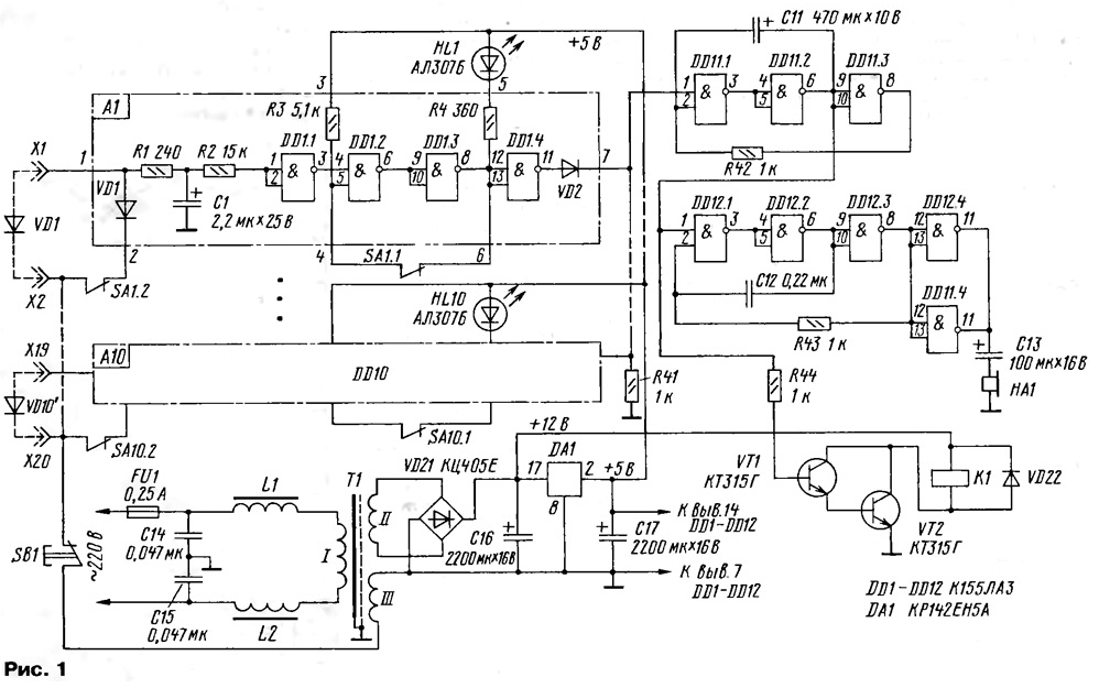
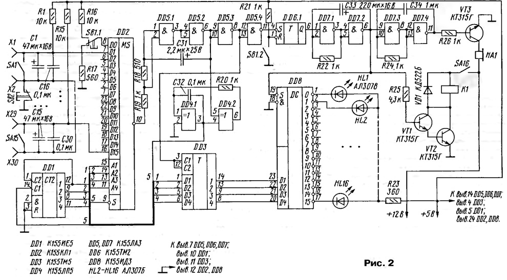
Encyclopedia of radio electronics and electrical engineering / Safety and security The article offers a description of two relatively simple, reliable and inexpensive autonomous security and alarm devices with 10 and 15 locking lines. The proposed devices are simple, so they can be made by averagely qualified radio amateurs. The number of blocking lines in the first version of the device can be any, depending on the number of linear cells (for example, the value is 10), and in the second - up to 15. The loop resistance is 0...2 kOhm (first option) and 0... 1 kOhm (second). Power consumption is 4 and 3,5 W, respectively. The response time to a line break is about 200 ms. The scheme of the first version of the device is shown in fig. one. To control the blocking line (hereinafter referred to as LB), there is a linear cell outlined in the diagram with a dash-dotted line. All other cells are identical, so the number of cells is in principle unlimited and is determined only by needs and design considerations. An alternating voltage of about 1 V is supplied from winding III of transformer T20 to the LB. A diode installed at the end of the LB, which is a privacy element, rectifies the current and in negative polarity (with the SA1.2 toggle switch contacts open) through filter R1C1R2 it is supplied to the inputs of element DD1.1 . The relatively high voltage supplied to the LB significantly increases the noise immunity of the device. In order for the microcircuit to switch, the amplitude of the noise induced in the LB must be at least 20 V. This is unlikely even in an industrial enterprise. In the position of the toggle switch SA1 shown in the diagram, the object is disarmed, since the contacts SA1.2 connect the diode VD1 to the input of the linear cell, which serves as the equivalent of the LB. At the inputs of the element DD1.1 there is a low level, at the output DD1.3 it is high, the HL1 LED does not emit. To arm an object, you need to switch toggle switch SA1 to the position where its contacts are open. Contacts SA1.2 turn off diode VD1, and a blocking line is connected to the input of the linear cell. Contacts SA1.1 close a circuit that turns elements DD1.2 and DD1.3 into a trigger. When the LB opens (alarm mode), the trigger switches to the zero state and remains in it regardless of the LB state, so the HL1 LED lights constantly, indicating the number of the blocking line that generated the alarm. The high level from the output of element DD1.4, through the decoupling diode VD2, goes to pin 1 of element DD11.1 and enables the operation of an audio frequency pulse generator assembled on elements of microcircuits DD11 and DD12. Elements DD11.4 and DD12.4 are connected in parallel, and their outputs are loaded onto the telephone capsule HA1. Additional light and sound signals are activated using relay K1. The relay contacts are not shown in the diagram. To monitor the health of linear cells, use the SB1 button, the contacts of which break the 20 V circuit. This causes the simultaneous ignition of all LEDs, regardless of the state of the LB and toggle switches SA1 - SA10. The power supply is assembled according to a standard design and has no special features. Relay K1 is powered by an unstabilized voltage. All resistors are MLT-0,125. Oxide capacitors - K50-16, K50-35, capacitors C14, C15 - K73-17 for an operating voltage of 400 V. Relay K1 - RES-9, passport RS4.529.029.02 or another for an operating voltage of 7...8 V. Toggle switches - TP1-2, you can also use P2K. Telephone capsule NA1 - TK-67. Transformer T1 is wound on a magnetic core ШЛ 16x20. The primary winding contains 3700 turns of PEV 0,1 wire. Winding II has 138 turns of PEV 0,5 wire. Winding III contains 346 turns of PEL 0,1 wire. An electrostatic screen is laid on top of the primary winding in the form of an open coil of copper foil, which is connected to a common wire. Between the windings and the screen it is necessary to lay 2-3 layers of paper or varnished cloth. If there is no foil, you can wind one layer of wire with a diameter of 0,3...0,5 mm. In this case, one end is connected to a common wire, and the other is isolated. In the second version of the security alarm device, the idea described in the article by S. Biryukov “Quasi-sensory switches and keyboards with dynamic polling” (Radio Yearbook, 1986, p. 112) is used, which makes it possible to control 15- XNUMX or more LB. The idea is to use a multiplexer to scan the state of the blocking lines. The scheme of the second variant is shown in fig. 2. The clock pulse generator required for the operation of the counter and multiplexer is assembled on two “EXCLUSIVE OR” elements - DD4.1 and DD4.2. Pulses from the generator output are supplied to input C1 of counter DD1. Its outputs are connected to the address inputs of the multiplexer DD2. The same pulses strobe the multiplexer at the S input to clearly determine the number of the LU that generated the alarm. Resistors R1-R15 and the resistance of the blocking lines form dividers to which the multiplexer inputs are connected. When the LU is closed, the voltage at the multiplexer input should not exceed the logical zero voltage. If the LB resistance is about 1 kOhm, the resistance of the upper arm of the divider should be at least 10 kOhm. However, it turned out that increasing the resistance of the upper arms leads to unstable operation of the multiplexer. The author experimentally found that connecting an additional resistor R19 at the multiplexer output solves the problem quite satisfactorily. Oxide and ceramic capacitors shunting the LB reduce the likelihood of false alarms due to the effects of impulse noise. While all LUs are working properly, there is a low level at the inputs D of the multiplexer DD2, and a high level at the output. A high level at the output of element DD5.2 allows the generator to operate. When any LU is opened, a high level appears at the corresponding input of DD2, and a low level appears at the output. Through the debounce circuit R18C31DD5.1DD5.2, the signal is supplied to input 5 of element DD4.2. A low level at this input prohibits the operation of the generator, and the address code of the faulty LU is recorded at the output of counter DD1. This code is transmitted to the DD3 chip, which serves as a memory element. The code is written to it at a high level from the output of element DD5.3. From the outputs of the DD3 chip, this address is transmitted to the inputs of the DD8 decoder, and a low level appears at its corresponding output. The LED lights up, indicating the LU number. A low level from the output of element DD5.4 switches trigger DD6, which, with a high level at its output, allows the generator to operate on elements DD7.1 and DD7.2. Pulses with a frequency of about 1 Hz are supplied to the enabling input S of the DD8 decoder, so the LED blinks at this frequency. The signal from output DD7.2 is also supplied to transistors VT1 and VT2, which turn on relay K1. Its contacts (not shown in the diagram) control the loud bell and warning lamp installed outdoors. The generator based on elements DD7.3, DD7.4 is designed to produce an intermittent sound signal. Since when an alarm signal is issued from any LB, scanning of the remaining LBs stops, to resume the security mode on the remaining blocking lines, it is necessary to turn off the LB broken by the sensor. This can be done (immediately after receiving an alarm signal) by setting the corresponding toggle switch SA1-SA15 in "OFF" position. With its contacts it bypasses the line, supplying a low level to the corresponding input of the multiplexer. The latter goes back to scanning the LB and restores the security mode. Of course, this is a drawback of this system. But as practice has shown, the staff on duty, trying to get rid of alarm signals as quickly as possible, immediately makes the necessary switches. After the faulty LU is turned off, the alarms continue to sound and the LED flashes. To reset the alarm and return the device to its original state, press the "RESET" button. Its SB1.2 contacts switch the DD6 trigger to the zero state, and the generators stop working. Contacts SB 1.1 transfer the decoder to address zero. The green LED HL1 lights up, signaling the establishment of the security mode. Button SB2 is used to check the health of the system. When it is pressed, all outputs of the multiplexer are high, but the alarm will only appear at one randomly selected address. The power supply of the second option is assembled according to the same circuit as for the first, winding III of transformer T1 is excluded. In both versions, all microcircuits are power-blocked by ceramic capacitors with a capacity of 0,1 μF. They are not shown in the diagrams. Operation of the devices for seven years has shown their high reliability. Even a lightning strike in the immediate vicinity of the device installation site only led to the breakdown of one oxide capacitor at the LB input. Operating the device does not cause any difficulties for the personnel on duty, which cannot be said about industrial devices. Maintenance was reduced only to periodic removal of dust and replacement of failed toggle switches. Author: R. Ushakov, Zelenogorsk, Krasnoyarsk Territory
Machine for thinning flowers in gardens
02.05.2024 Advanced Infrared Microscope
02.05.2024 Air trap for insects
01.05.2024
▪ Mercedes will make trucks more economical ▪ Invisible system to protect bicycles from theft ▪ Flexible electrically conductive ceramic paper ▪ Toyota FCET hydrogen fuel cell truck
▪ section of the site Firmware. Article selection ▪ Nemesis article. Popular expression ▪ What planets have rings? Detailed answer ▪ Sedan article. Legends, cultivation, methods of application ▪ article Antenna Mussel. Encyclopedia of radio electronics and electrical engineering
Home page | Library | Articles | Website map | Site Reviews www.diagram.com.ua |


 Arabic
 Bengali
 Chinese
 English
 French
 German
 Hebrew
 Hindi
Hindi Italian
 Japanese
 Korean
 Malay
Malay Polish
 Portuguese
 Spanish
 Turkish
 Ukrainian
 Vietnamese


 Leave your comment on this article: