|
|


 Arabic
 Bengali
 Chinese
 English
 French
 German
 Hebrew
 Hindi
Hindi Italian
 Japanese
 Korean
 Malay
Malay Polish
 Portuguese
 Spanish
 Turkish
 Ukrainian
 Vietnamese
|
ENCYCLOPEDIA OF RADIO ELECTRONICS AND ELECTRICAL ENGINEERING Device for acoustic diagnostics of bee colonies. Encyclopedia of radio electronics and electrical engineering
Encyclopedia of radio electronics and electrical engineering / Home, household, hobby The profitability of beekeeping farms depends on the performance of bee colonies during the period of honey collection. Great economic damage to large apiaries, numbering several hundred beehives, is caused, for example, by uncontrolled swarming. Many technological methods have been developed to prevent it, but all of them are very laborious, require disassembly of the hives and intervention in the life of the bee colony. In order to successfully apply these techniques, it is very important to determine the biological state of bees in a timely and accurate manner. The proposed device will help to do this. Attempts to design a device for acoustic diagnostics of the biological state of bee colonies have been made repeatedly [1]. The principle of operation of most known devices is that a narrow frequency band centered at a frequency of 240 Hz is isolated from the acoustic noise created by the bee colony by a filter. It is assumed that the presence of components with frequencies close to the specified one in the noise spectrum indicates a low activity of bees. But tests of such devices in real conditions do not give positive results. The main reason for their unsatisfactory work is the wrong choice of criterion for assessing the state of the bee colony. The fact is that components with frequencies close to 240 Hz are always present in the noise created by bees. Their intensity depends not only on the biological state of the colony (for example, swarming), but also on other factors, such as the number of bees in the hive. Therefore, the readings of instruments that measure the absolute value of the noise intensity are unreliable, and the instruments themselves are unsuitable for beekeeping practice. In order for the readings of the device to depend only on the biological state of the bee colony, it is necessary to evaluate the ratio of the intensities of two narrow-band noise signals isolated in different frequency regions. In [2] it is shown that the active state of the bee colony (spring development, honey flow) is characterized by the maximum intensity of the spectral components in the frequency band of 260...320 Hz. With a decrease in activity (swarming, disease, absence of a queen), the maximum of the spectrum shifts to the region of 210...250 Hz. Having determined in which of the indicated ranges the noise intensity is greater, one can judge the state of the bees. The proposed acoustic diagnostic device, operating on this principle, is equipped with two LED indicators: "Yes" and "No". Three modes of operation are provided. The first of them - "P" (passive state) - is designed to identify the non-working state of the bee colony, associated, for example, with swarming, lack of space for brood or overloading the nest with honey. Weak compared to the "Yes" indicator, the glow of the "No" indicator means that inactive bees are accumulating in the hive and the bee colony will enter the swarm stage in the coming days. In the "M" mode (reception of the queen), the attitude of the family to the transplanted queen bee is revealed, which can be accepted ("Yes") or rejected ("No"). The state of wintering bees is assessed in mode "3" (wintering). It is satisfactory if the "Yes" indicator is on, or bad otherwise. The scheme of the device is shown in fig. 1. A two-stage amplifier with automatic gain control, built on the DA1 chip (K157UD2), is designed to amplify the audio signals received by the BM1 microphone. A passive band-pass filter C3R2R4C5 is installed between the two stages of the amplifier, passing frequencies from 160 to 890 Hz.
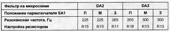
The signal from the output of the op-amp DA1.2 is fed to the inputs of the band-pass filters, and through the resistor R3 - to the telephone capsule BF1 for auditory control. The same signal is sent to the AGC detector (VD1). A change in the noise level leads to a change in the bias at the gates of field-effect transistors VT1.1, VT1.2, the resistance of their channels and the depth of feedback that the amplifier stages cover. As a result, when the intensity of the noise generated by the bee colony fluctuates, the signal voltage at the output of the amplifier is maintained unchanged. Two bandpass filters extract narrow sections from the noise spectrum, the ratio of signal levels in which carries information about the state of the bees. Both filters are built according to the same schemes on DA2 and DA3 microcircuits. The op-amps of each of them are connected in such a way that they form gyrators. The equivalent inductances of the gyrators are parallel oscillatory circuits with capacitors C9 and C10. The quality factor of the circuits and the bandwidth of each filter depend on the values of the resistors R8 and R9. With tuned resistors R11, R13, R15 and R18 (depending on the position of switch SA1), the filters are tuned to the frequencies indicated in the table.
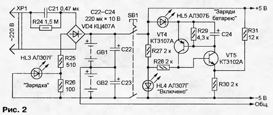
With the help of resistors R12 and R14, the maximum quality factor of the circuits is achieved: with the jumpers X1 and X2 removed, the filters should be at the self-excitation border. The filtered signals through half-wave rectifiers on diodes VD2 and VD3 are fed to the inputs of a differential amplifier based on transistors VT2 and VT3, which serves as a comparison node. The collector circuits of the transistors include LEDs HL1 ("No") and HL2 ("Yes"), the comparative brightness of which indicates the state of the bee colony. The scheme of the power supply unit of the device is shown in fig. 2, and the numbering of elements continues that started in Fig. 1. Two GB1 and GB2 batteries are installed here. Each consists of four batteries D-0,26. The device is switched on by a push-button switch SB1. The current consumption does not exceed 25 mA, and fully charged batteries are enough for 2000 measurement sessions with a duration of 5 s.
The trigger on transistors VT4, VT5 of different structures is used to control the voltage of the batteries. An exemplary is the voltage drop across the HL4 LED, signaling the inclusion of the device. When the total voltage of the batteries GB1 and GB2 is above 7 V, the voltage drop across the resistor R30 exceeds the exemplary one, the transistors VT4 and VT5 are closed, the HL5 LED is off. When the battery voltage is below the specified trigger changes state, its transistors open, LED HL5 signals the need to charge the batteries. The battery charging unit from the mains is made according to the simplest scheme with a quenching capacitor C21. It also includes a diode bridge VD4 and resistors R24 - R31. During charging, the HL3 LED lights up. Full recovery of battery capacity takes 14 hours. The design of the device can be any. It is important to ensure that it is easy to use and carry. In the author's version, it has dimensions of 260x180x70 mm and weighs 1,4 kg. A 3H generator and an AC millivoltmeter are required to set up the scan tool. The millivoltmeter is connected to the output of the first band-pass filter (pin 13 of the DA2 chip) and a common wire. After removing the jumper X1, the trimming resistor R12 enters the filter into the generation mode, fixing the occurrence of oscillations by the deviation of the millivoltmeter needle. A slight turn of the axis of the resistor R12 in the opposite direction disrupts the generation. The output of the 3H generator is connected to the left terminal of the resistor R8 according to the circuit and, operating with the SA1 switch and trimmers R11 and R15, tune the filter to the frequencies indicated in the table. Start tuning with resistor R11 by setting switch SA1 to position "3". In the positions "M" and "P" the found position of the axis of this resistor does not change. By connecting a millivoltmeter to pin 13 of the DA3 microcircuit and removing the jumper X2, in a similar way, using the trimmer resistor R14, they achieve generation and its disruption in the second filter. Then the filter is tuned to the desired frequencies with trimmers R13 (SA1 - in the "3" or "M" position) and R18 (in the "P" position). After completing the configuration, jumpers X1 and X2 are installed in place. The operation of the device as a whole can be checked by applying a 3H generator signal to a small dynamic head and placing it next to the BM1 microphone. When tuning the oscillator frequency, the maximum brightness of the HL1 and HL2 LEDs should correspond to the tuning frequencies of the corresponding filters and depend little on the volume of the sound. To check the condition of the bee colony, the microphone of the device is placed on a canvas covering the frames with bees. An insulating pillow is placed on top to dampen outside noise. The device is turned on for a few seconds, watching the LEDs HL1 and HL2. Diagnostics in the "M" mode is carried out after the queen bee is placed in the hive in the "Titov's cage". After about half an hour, you can determine whether it is accepted by the bees. Literature
Author: I.Bakomchev, Ulyanovsk
Machine for thinning flowers in gardens
02.05.2024 Advanced Infrared Microscope
02.05.2024 Air trap for insects
01.05.2024
▪ Miracle laptop with 6,8 GHz processor 1 TB RAM ▪ 3D printer with voice control ▪ Food from insects will create waste-free agriculture ▪ High-speed optical communication Li-Fi ▪ Combination of lanthanum and hydrogen broke the superconductivity record
▪ site section Electrician's tool. Article selection ▪ Article Wives and children to lay. Popular expression ▪ article Was there a bird that looked like a dodo? Detailed answer ▪ Chinar article. Legends, cultivation, methods of application ▪ article The Secret of the Nine. Focus Secret
Home page | Library | Articles | Website map | Site Reviews
www.diagram.com.ua |


 Leave your comment on this article: