|
|


 Arabic
 Bengali
 Chinese
 English
 French
 German
 Hebrew
 Hindi
Hindi Italian
 Japanese
 Korean
 Malay
Malay Polish
 Portuguese
 Spanish
 Turkish
 Ukrainian
 Vietnamese
|
ENCYCLOPEDIA OF RADIO ELECTRONICS AND ELECTRICAL ENGINEERING capacitive sensor. Encyclopedia of radio electronics and electrical engineering
Encyclopedia of radio electronics and electrical engineering / Security devices and object signaling The device reacts to the approach of a hand to a metal object, such as a lock, safe, or to the touch of a protected object. Any electrically conductive plate with dimensions of approximately 200x200 mm can also serve as a sensor. The sensitivity of the sensor depends on the setting and can be up to 20 cm. A distinctive feature of the above schemes of capacitive sensors is their low consumption (operation in the microcurrent mode), which allows the use of autonomous power supply. The operation of the circuit (Fig. 3.34) is based on the principle of variable capacitance. When you bring your hand to the WA1 sensor, a capacitance is introduced into the oscillatory circuit of the oscillator on the transistor VT1, and its frequency changes. The initial frequency of the oscillator is about 280 kHz. The circuit is tuned so that the second oscillatory circuit (L2, C7) is in resonance with the frequency of the oscillator. An active RF signal detector is assembled on the VT4 transistor. With a sufficient voltage amplitude in the circuit (L2, C7), VT4 will be in saturation (while VT5 is locked).
A chain of resistors R6, R7 ensures stable operation of the circuit when the supply voltage changes from 3,5 to 10V. Resistor R6 can set the desired sensor sensitivity. Transistors VT2 and VT3 are used as diodes to stabilize the operating modes of transistors VT1 and VT4 when the supply voltage changes. Compared to diodes, a transistor junction provides better voltage regulation at low operating currents. For the convenience of setting up the circuit, an LED with a limiting resistor can be connected to the VT5 collector (the value of the resistor depends on the supply voltage and can be from 200 to 1000 ohms).
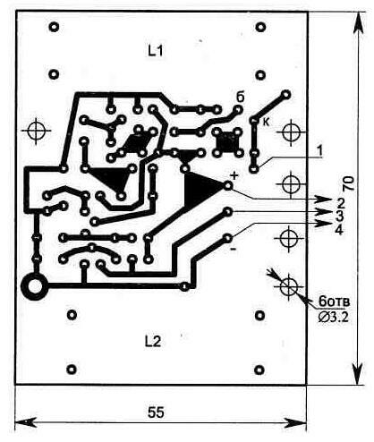
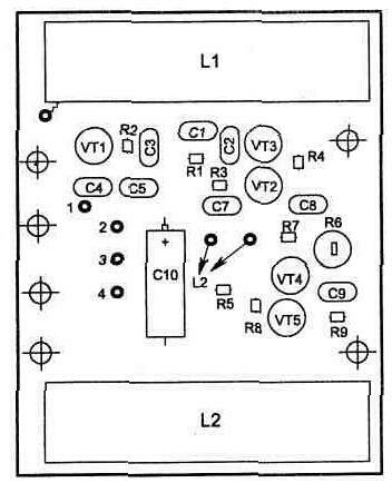
Rough tuning of the circuit is performed by capacitor C7, smooth - by the core of the coil L2, as well as resistor R6. The final setup of the device is carried out with a real WA1 sensor, with which the circuit will work in the future. In this case, if the protected object has a large metal surface, then it may be necessary to install an isolation capacitor of small capacity (5 ... 100 pF) between WA1 and pin 1 of the circuit. Coils L1, L2 are wound on a 600НН (or 400НН) type ferrite rod with a diameter of 10 mm and a length of 55 mm (see Fig. 3.35). Such ferrites are used as an antenna in receivers on the MW and LW bands. Coil L1 contains 350 turns, L2 - 250 turns of PELSHO wire with a diameter of 0,08 ... 0,12 mm, which are evenly distributed over a paper frame on a ferrite rod. Core L2 must move relative to the frame. Fixed resistors used type C2-23, tuning R6 - SPZ-19a, capacitor C10 type K53-1, the remaining capacitors type K10-17. On fig. 3.36 and 3.37 shows the design of the printed circuit board and the location of the elements on it. The sensor circuit is placed in any plastic housing and is mounted near the WA1 (100 ... 200 mm) sender. The device can work in conjunction with other security schemes as a sensor or as an independent security device with an audible indicator (Fig. 3.38). The parameters of the coils L1, L2 are the same as in the circuit shown in fig. 3.34, the L3 coil is wound on two ferrite rings glued together (600 ... 2000NN) of the KYuhbhZ size and contains 250 turns of the same wire (its inductance is about 120 mH).
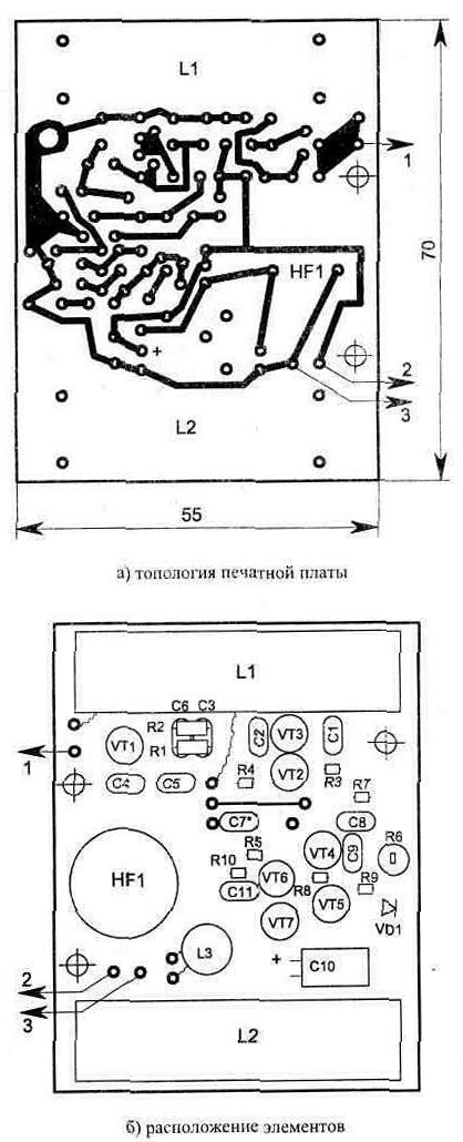
The principle of operation of the sound generator on transistors VT6 and VT7 is similar to the diagram shown in fig. 4.12. Any piezo emitter is suitable as a sound source HF1, but the topology of the printed circuit board (Fig. 3.39) is given for the installation of ZGI 8.
On the board, resistors R1 and R2 are located above the capacitors, which increases the mounting density, and capacitor C10 is used of the K50-16 type for 16 V. When the circuit is powered from a source with a voltage of 6 V, the current consumption in the ARMED mode does not exceed 1 mA, and with an audible signal - 3 mA. Publication: cxem.net
Artificial leather for touch emulation
15.04.2024 Petgugu Global cat litter
15.04.2024 The attractiveness of caring men
14.04.2024
▪ The divine wind was helped by hack-workers-shipbuilders ▪ New material for the bone frame ▪ Panasonic will create TVs 16 times clearer than Full HD ▪ A new type of tablet from Lenovo
▪ site section Lightning protection. Article selection ▪ article Dying swan. Popular expression ▪ article Hyssop angustifolia. Legends, cultivation, methods of application ▪ article Japanese coaxial cables. Encyclopedia of radio electronics and electrical engineering
Home page | Library | Articles | Website map | Site Reviews
www.diagram.com.ua |


 Leave your comment on this article: