|
|


 Arabic
 Bengali
 Chinese
 English
 French
 German
 Hebrew
 Hindi
Hindi Italian
 Japanese
 Korean
 Malay
Malay Polish
 Portuguese
 Spanish
 Turkish
 Ukrainian
 Vietnamese
|
ENCYCLOPEDIA OF RADIO ELECTRONICS AND ELECTRICAL ENGINEERING USB interface converters based on FT8U232AM, FT8U245AM chips. Encyclopedia of radio electronics and electrical engineering
Encyclopedia of radio electronics and electrical engineering / Computers Now you will not surprise anyone with the ability to connect USB devices to a computer. Compared to traditional computer I / O ports (serial - COM, parallel - LPT), the universal serial bus (Universal Serial Bus) provides a higher data exchange rate. The maximum throughput of USB version 1.1 is 12 Mbps, the more recent version 2.0 is 480 Mbps. For low-speed devices, a speed of 1,5 Mbps is provided. However, the USB data exchange protocol is complicated and until recently it was not possible to implement it not only for radio amateurs, but also for many specialists. Today, by installing the FT8U232AM or FT8U245AM chip in the device being developed, you can convert USB into a "virtual" serial or parallel port and conduct high-speed data exchange using familiar well-known methods, without taking into account many features of USB operation. Connecting your computer to peripherals using USB is very easy. It is allowed to dock and undock connectors without turning off the computer, automatic device recognition is provided immediately after it is connected, followed by installation of the necessary drivers. The branched bus topology (Fig. 1) involves the use of hubs, often called "hubs" (English hub).
The system unit of the computer has a root hub (root hub), equipped with two or four USB sockets, to which peripheral devices are connected directly or through hubs. Sometimes USB devices themselves (most often a monitor and a keyboard) are equipped with built-in hubs, in other cases, hubs designed as independent products are used to branch the bus. An example of connecting a conventional set of peripheral USB devices to a computer is shown in fig. 2. Their total number can reach 127 - more than enough for all conceivable applications. Until recently, the "host" (host) of this network (unlike the usual local) could be only one - the computer itself. However, an addition to the USB 2001 standard published at the end of 1.0 under the name OTG 2.0 allowed peripheral devices to perform some host functions. This will allow, for example, to connect a USB scanner directly to a USB printer, bypassing the computer.
Each connected USB device is assigned a unique identification number by the computer's operating system, which is necessary for system configuration, management, and communication. Communication sessions occur in batch mode. All components of the USB network are connected using cables consisting of two twisted pairs of wires. On one of them there is a two-way data exchange, on the other - a constant voltage of 5 V, due to which economical peripheral devices may not contain their own power supplies. USB cables have two incompatible types of connectors: A on the side facing the computer and B on the side facing the peripheral. This prevents erroneous connection. According to the OTG 1.0 addition mentioned above, two more types of reduced dimensions connectors have been introduced: mini-A and mini-B, as well as a mini-AB universal socket that is compatible with both types of plugs. All USB connectors are designed to be quickly and easily plugged in and out repeatedly. The scope of USB is not limited to multimedia applications. This high-speed interface, designed to serve a large number of devices, is convenient for communication equipment, information collection and storage, which is traditionally connected to the COM and LPT ports of computers. Unfortunately, replacing an interface in an existing device is quite difficult. One way to solve the problem is to use converters of various interfaces to USB. Similar devices based on chips from the English company FTDI (Future Technology Devices International) are already appearing on the Russian market. The company currently produces three multifunctional chips: FT8U100AX, FT8U232AM and FT8U245AM. The first of them allows you to create a seven-port USB hub. The other two (their appearance and pin assignments are shown in Fig. 3) are designed to interface various devices with the USB bus. The dimensions of the QFP-32 package are 7x7 mm, the pin pitch is 0,8 mm.
FT8U232AM - USB to traditional serial interface converter - can be installed in USB modems, COM-USB adapters, barcode scanners, measuring equipment - in fact, in any devices that previously used relatively slow RS-232, RS-422, RS-485 interfaces. It is capable of transmitting data in both directions at speeds up to 2000 kbps, and the user does not need any knowledge about the device and the operation of USB. The software drivers supplied by FTDI give the impression that the communication is going through a regular COM port. the functional diagram of FT8U232AM is shown in fig. 4. Its basis is the transceivers of both interfaces. The UART block is equipped with a full set of signal circuits of the RS-232 standard, the USB transceiver - with only two information outputs USBDP and USBDM, forming a bidirectional data transfer channel. The SIE block converts serial code to parallel and vice versa, performs bitstaffing procedures, generates (for outgoing data stream) and checks (for incoming) control codes.
The low-level USB protocol handler generates responses to requests from the host controller (computer). Through it, they control the operating mode of the UART. There are two intermediate data storage buffers (FIFO) with a capacity of 384 bytes (for reception) and 128 bytes (for transmission). The FIFO is managed by the appropriate controller. The master oscillator of the microcircuit is powered by an external quartz or ceramic resonator at 6 MHz. Further, its frequency is multiplied by 8 (up to 48 MHz). The UART clock is obtained from 48 MHz in two steps: by dividing by 16, then to the desired value using a programmable divider. The UART controller can operate at speeds from 300 baud to 2 Mbaud, but the actual maximum achievable speed depends on the level converter IC used with the FT8U232AM. The EECS, EESK, EEDATA pins of the FT8U232AM chip are designed to connect external non-volatile memory - the AT93C46 EEPROM chip, which stores the manufacturer's identifiers (VID) and personal (PID) serial number of the product and other data. This is necessary if several devices based on FT8U232AM chips are simultaneously connected to the computer via USB. The serial number is especially important, since the software driver relies on its uniqueness, associating one or another virtual COM port with a specific device. If there is no ROM, only one device that forms a virtual COM port can be connected to the computer. A low level at the RESET input causes the FT8U232AM chip to reset. An RC circuit must be connected to the RCCLK pin, which delays the start of the microcircuit for a time sufficient to "build up" the quartz resonator connected to the XTIN, XTOUT pins. The TEST input is only used in debug mode. In normal operation, it must be connected to ground (GND). There are several auxiliary outputs. A high level at the USBEN output indicates the completion of the microcircuit initialization process via USB. If there is no data exchange for some time, the microcircuit automatically switches to "sleep mode", as evidenced by the low level at the SLEEP output. Similar levels at the TXLED and RXLED outputs indicate that data is being transmitted or received, respectively. The signal from the TXDEN output is designed to control the transceiver of the RS-485 interface. Its level is high when data is being transmitted on the TXD line. The supply voltage of the FT8U232AM microcircuit (VCC) is 4,4 ... 5,25 V, the current consumption is not more than 50 mA in operating and 250 μA in sleep modes. If the microcircuit is powered by voltage supplied via USB, its pin 14 (PWRCTL) must be connected to ground (GND), if the device has its own power supply - to the VCC circuit. The logical outputs of the microcircuit are designed for current up to 4 mA (outflow) and up to 8 mA (inflow). The FT8U245AM chip allows you to organize data exchange between a peripheral device and a computer at a speed of up to 1 Mbps. It can be used in ISDN and ADSL modems, in digital cameras and MP8 players, in measuring equipment. Unlike the FT245U0AM, it does not contain a UART block, issuing data received via USB from a buffer (FIFO) or receiving them there via an eight-bit parallel bidirectional data bus (D7 - DXNUMX). This chip interfaces conveniently with any microprocessors and microcontrollers using their Direct Memory Access (DMA) channels or I/O ports. Timing charts for reading and writing a byte are shown in fig. 5.
The presence of data received via USB (the size of the receive buffer is 128 bytes) is indicated by the low level of the RXF signal. Data is read until the buffer is empty and RXF is high. After filling all 384 bytes of the transmit buffer, the TXE signal remains high and the microcircuit ceases to accept new data until the contents of the buffer are transferred via US B to the computer. In order not to delay the exchange, a timer of 16 ms is provided. If the send buffer is not full within this interval and no new data arrives, the contents of the buffer are automatically sent to the computer. The FT8U232AM chip has a similar property. For hardware developers who master the FT8U232AM and FT8U245AM chips, GIGATECHNO-LOGY offers debug modules, one of which is shown in fig. 6.
In addition to the microcircuit, the board contains all the passive elements necessary for its operation, a quartz resonator and a USB type B socket. The module is installed in a standard 32-pin "wide" DIP-panel. The module is powered by USB, which eliminates the need for an additional source. The diagram of the completed USB-RS-232 interface converter is shown in fig. 7. With it, many devices equipped with an RS-232 interface can be connected to a computer via USB. The converter is connected to a computer (or hub) using a USB type A (CN1) plug, equipped with a 1,5 m connecting cable. Do not increase the length beyond the specified one, otherwise the USB will malfunction.
The U3 FT8U232AM chip is connected according to the standard scheme recommended by the manufacturer. The node on the transistor Q1 at the moment of power supply (connecting the converter to the USB network) generates a pulse that resets the U3 chip. The supply voltage is supplied to the converter nodes through the filters FB1 and FB2 - ordinary wires with ferrite washers put on them. The R5C10 circuit creates a delay for the start of the generator on the Y1 resonator, which can be used as imported HC49U, domestic PK415, etc. If the resonator is two-terminal and does not contain built-in capacitors, it may be necessary to install external capacitors with a capacity of 10 ... 20pF. Chip U1 contains receivers and transmitters of interface signals that meet the RS-232 standard, as well as voltage converters 5 V to +10 and -10 V, necessary for their operation. The SP213EHCA (Sipex) chip shown in the diagram provides a data exchange rate of up to 460 kBaud. If 115 kBaud is sufficient, the specified chip can be replaced with the SP213ECA of the same company, MAX213CAI (Maxim) or ADM213EARS (Analog Devices). Chip U1 93C46, as already mentioned, is not required. If you decide to install it, you must first program it using the recommendations in the appendix to the description of the FT8U232AM chip. This document and many other useful technical and reference information can be found on the FTDI website. . The appearance of the converter is shown in fig. 8. Its PCB is housed inside the DB-9M plug housing.
It should be noted that the developed board, the drawings of the layers of which are shown in Fig. 9, - four-layer.
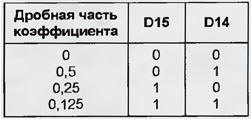
It is designed for installation of elements on both sides, including resistors and capacitors of size 0603 (1,6x0,8 mm) for surface mounting (SMD). In amateur conditions, such a board can be made from two double-sided boards glued together through an insulating gasket. All documentation required for the manufacture of the board in the factory If it is not possible to use SMD elements and make a multilayer board, you will have to independently develop a regular one for standard elements. INSTALLING VIRTUAL COM DRIVERS Virtual COM port driver (VCP - Virtual COM Port) for any operating system of interest can be found on the official FTDI website in the topic section Drivers and Utilities. VCP drivers are available in two versions: for devices connected via an interface converter and supporting the technology (Plug and Play PnP), and similar devices without such support (Pop-PnP). An error in choosing a driver leads to a delay in loading the operating system by 20...30 s. The procedure for installing a VCP driver in Windows is no different from installing a driver for any other device. All files from the archive in which the driver is supplied must be copied to a floppy disk or to a specially created folder on the hard disk. Next, having connected an interface converter (or another device based on FT8U232AM, FT8U245AM chips) to USB, open the "Add/Remove Hardware" window and follow the instructions of the "Installation Wizard". To verify that the drivers have been successfully installed, open the "Device Manager" tab in the "System Properties" window and find USB High Speed Serial Converter in the list. If there is nothing similar there, the installation procedure should be repeated again. After successful installation of the drivers, the USB Serial port (COMx) device will appear in the USB High Speed Serial Converter item, where x is the number of the virtual serial port. The basic parameters of COMx are identical to the parameters and settings of a standard serial port. You can change the UART speed, number of bits per word, parity mode, stop bit length, flow control method. The only difference is the ability to select or change the port number x in the "Advanced Port Settings" window. As a virtual COM port programming tool for Windows 98, you can use the standard VCOMM API family of functions. Documentation and other useful information on their use is contained in MSDN (Microsoft Developer Network). FTDI offers another solution that does not require serial emulation drivers. The architecture, called D2XX by its authors, is based on WDM technology. The device is programmed through the USB stack and the dynamic library of the driver. The company's website contains source code examples in several popular programming languages, as well as the D2XX Programmers Manual. BAUD RATE SETTING Information about the values of the clock frequency division factor by the programmable divider of the FT8U245AM chip, which are necessary to obtain a particular data exchange rate, is contained in the ftdiport.inf file that accompanies the driver. By changing these values, you can achieve non-standard UART speeds. However, more often they have to be changed to take into account, for example, the frequency deviation of the quartz resonator from the nominal 6 MHz. To calculate the desired division factor, a number half the frequency of the quartz resonator (Hz) is divided by the required baud rate (Baud). The quotient is rounded off to the nearest number with a fractional part of 0,125, 0,25, 0,5 or to a whole number. The resulting value must be converted to a 16-bit binary code. In the 14 least significant digits of the code (D0-D13), the integer part of the coefficient is entered, and in the senior ones (D14, D15) - the fractional part in accordance with the table. This code is then converted to a two-byte hexadecimal number.
On a Windows 98 system, in the [FtdiPort232.HW.AddReg] section of the ftdiport.inf file mentioned above, look for the line HKR,,configData,1,01,00,3F.3F,10,27,88,13,C4,09,E2,04,71,02,38,41,9C,£0,4E,CO,34,00,1A,00,0Dt 0,06,40,03, 80,00,00, 00, 00 Please note that it is divided into several lines conditionally, and in the file it must be written as a single one, without spaces. Coefficient values that can be changed are shown in bold and italic alternately for convenience. No selections are allowed in the file. The low byte of each coefficient is written first, followed by the high byte. For example, the sequence E2,04 corresponds to the number 4E2H. Having made the necessary changes, the edited file is replaced with the original one. Working in Windows 2000, edit the same line in the [FtdiPort232.NT.HW.AddReg] section of the same file in the same way. Authors: A. Lysenko, R. Nazmutdinov, I. Malygin, Yekaterinburg
Artificial leather for touch emulation
15.04.2024 Petgugu Global cat litter
15.04.2024 The attractiveness of caring men
14.04.2024
▪ Music lessons contribute to academic success ▪ SAMSUNG High Performance High Capacity Chip Cards
▪ section of the site Dosimeters. Selection of articles ▪ article Who does not work, he does not eat. Popular expression ▪ article Head of the workshop. Job description ▪ article Thundering box. Focus Secret
Home page | Library | Articles | Website map | Site Reviews
www.diagram.com.ua |


 Leave your comment on this article: