log-periodic antenna. Encyclopedia of radio electronics and electrical engineering

Encyclopedia of radio electronics and electrical engineering / HF antennas
 Comments on the article
Modern requirements for a home-made amateur radio antenna can be reflected in several points:
- Provide operation on several bands, including WARC.
- Have a gain (relative to the dipole) of at least 5-8 dB and a back attenuation of at least 25 - 30 dB.
- The constructive implementation should be quite simple and not require large material costs. (If a radio amateur has the means, he can purchase an industrially manufactured antenna).
- Must have minimum SWR on all operating bands. This requirement is especially relevant for working on “branded” transceivers that do not have an automatic antenna tuner.
- It must be an electrically closed system, as it is least susceptible to electrostatic atmospheric noise.
- It should work without additional adjustment after lifting, which in practice is labor-intensive or impossible.
A log-periodic antenna can be proposed as the most suitable for these requirements, which is confirmed by the ever-increasing number of antennas of this type produced by well-known companies CushCrft, KLM, etc.
Structurally, the antenna is made on a conventional tubular boom.
The elements are made of lightweight duralumin tubes. My design consists of four-section antennas. The sections are inserted into one another and latched with spring locks. Such antennas are in short supply and radio amateurs can approach the manufacture of elements based on available materials. The diameter of the pipes does not matter much (which is also an advantage of Logoperiodic antennas) and can be made from antenna cable. Similar structures with a cord are described in the literature.
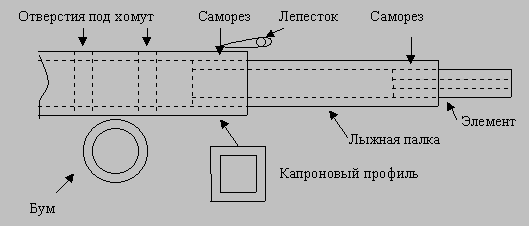
The insulation of the elements “broken” in the middle is carried out as follows: a square-section nylon profile is used (a water conduit used in agriculture), into which duralumin tubes (ski poles) with an outer diameter of 17 mm are pressed. The tubes of the elements themselves are inserted into them and secured with self-tapping screws. Two holes with a diameter of 8 mm are drilled in the middle of the nylon profile. for attaching to the boom with a clamp. The clamp is used from television antennas and has spikes that prevent the element from turning. Fastening of elements can be carried out in the traditional way on insulators on textolite or fiberglass platforms.

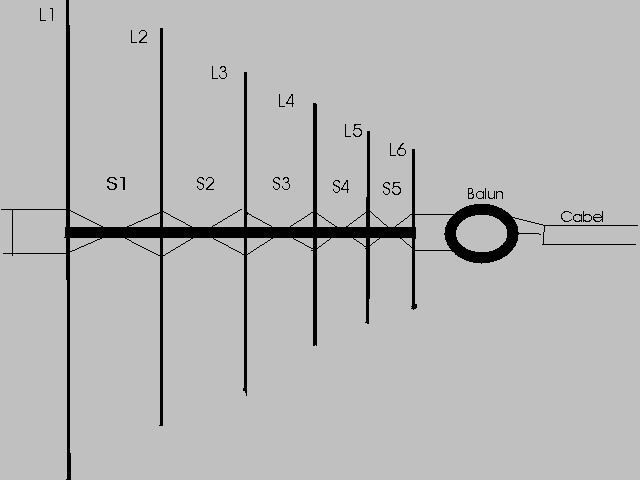
The antenna is powered by a standard symmetrical wire (collection) line made of copper wire with a cross-section of at least 1.5 mm in high-quality insulation and has two matching lines:
- C3adi (relative to the direction of radiation) is short-circuited, determining backward attenuation. This line additionally turns the antenna into a short-circuited system, which corresponds to paragraph 5 of the general requirements.
- In front there is a matching one and connected to a supply and balun HF transformer (balloon) having a ratio of 1:4. The balloon is wound on a ferrite ring having a magnetic permeability of 600 with two twisted wires in polyethylene insulation. Number of turns - 6. Ferrite - from the TV deflection system. The ring is disassembled into two halves and glued with glue with a ferrite filler, which sharply reduces power losses in it. A measurement was made of losses with equivalent load.

Accepted designations:
L1 is the length of the element.
S1- Distance between elements.
LS- Matching short-circuited line.
LC- Antenna power matching line.
B - Boom length.
K - Estimated coefficient.
t- Progression coefficient.
l- wavelength.
N is the number of elements.
Antenna size table from 14.000 to 29.000 mHz:
| LS=112 |
LC=64 |
t = 0.82259 |
K = 3.514 |
B = 600 |
| Element length L cm. |
Dist. between el. S see |
| L1 = 1070 |
S1 = 171 |
| L2 = 880 |
S2 = 141 |
| L3 = 724 |
S3 = 115 |
| L4 = 595 |
S4 = 95 |
| L5 = 490 |
S5 = 72 |
| L6 = 403 |
|
The antenna was assembled and raised to a height of 12 meters near a wooden country house using a lightweight telescopic mast. A cheap Chinese-made rotating mechanism was used, designed for rotating television antennas, purchased from the Radiospectr company.
The obtained technical parameters can be assessed as exceeding those specified at the beginning (except for 14 mHz, since the rise height is low for this range). Parameter measurements were carried out on all bands, including WARC with a radio amateur located at a distance of 15 km line of sight. The resulting characteristics are on average F / B - 54/56; F/S - 52; F/D - 59 +25db.
The accuracy of measurements is relative, adjusted for amateur radio equipment. Unfortunately, measurements with the GOS laboratory did not take place because The antenna is installed outside the city and there is no direct visibility.
The reflected wave coefficient throughout the entire range from 14 to 29 mHz turned out to be unchanged 1.3 at any measured point in the specified range. At frequencies of 13.2 and 30 mHz it tended to infinity. The measurements were carried out using an Icom-746 transceiver SWR meter.
It should be noted that the antenna is very “picky” about nearby metal objects and the lifting height. The antenna was first tested at a height of 7.5 meters and the test result at a frequency of 18 mHz showed that at this height the front lobe is blurred and the F/B ratio is no more than 5-8 decibels.
Some shortwave operators have a negative attitude towards Log Yagi antennas, considering them “noise collectors”. I agree with them on one condition - this occurs if a receiver is used with a preselector that has a wide range and a weak dynamic range. Conventional Yagi itself works as a preselector with good quality factor and reduces the requirements for receiver characteristics. Therefore, I advise shortwave operators to use an additional preselector or high-performance receiver when using Log Yagi; this will completely eliminate the problems caused by using Log Yagi.
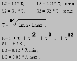
For shortwave operators who wish to calculate the antenna to suit their capabilities, the calculation formulas used to calculate the described design are given. The number of elements and the lower frequency are chosen arbitrarily. Not recommended, with an antenna range of 14 -28 mHz, the number of elements is less than 5/6 - the antenna efficiency drops sharply.
L1 = l/2; based on the lower operating frequency (14.0 mHz).
Ln = 405 cm for the upper frequency 29 mHz, based on a review of industrial and amateur radio designs (which contradicts the theory, but practical measurements confirm the correctness of the choice based on the measured SWR).

Author: R. Tarshish (RU3UJ), ru3uj@mail.ru; Publication: qsl.net/ru3uj
 See other articles Section HF antennas.
 Read and write useful comments on this article.
<< Back
 Latest news of science and technology, new electronics:
Machine for thinning flowers in gardens
02.05.2024
In modern agriculture, technological progress is developing aimed at increasing the efficiency of plant care processes. The innovative Florix flower thinning machine was presented in Italy, designed to optimize the harvesting stage. This tool is equipped with mobile arms, allowing it to be easily adapted to the needs of the garden. The operator can adjust the speed of the thin wires by controlling them from the tractor cab using a joystick. This approach significantly increases the efficiency of the flower thinning process, providing the possibility of individual adjustment to the specific conditions of the garden, as well as the variety and type of fruit grown in it. After testing the Florix machine for two years on various types of fruit, the results were very encouraging. Farmers such as Filiberto Montanari, who has used a Florix machine for several years, have reported a significant reduction in the time and labor required to thin flowers.
... >>
Advanced Infrared Microscope
02.05.2024
Microscopes play an important role in scientific research, allowing scientists to delve into structures and processes invisible to the eye. However, various microscopy methods have their limitations, and among them was the limitation of resolution when using the infrared range. But the latest achievements of Japanese researchers from the University of Tokyo open up new prospects for studying the microworld. Scientists from the University of Tokyo have unveiled a new microscope that will revolutionize the capabilities of infrared microscopy. This advanced instrument allows you to see the internal structures of living bacteria with amazing clarity on the nanometer scale. Typically, mid-infrared microscopes are limited by low resolution, but the latest development from Japanese researchers overcomes these limitations. According to scientists, the developed microscope allows creating images with a resolution of up to 120 nanometers, which is 30 times higher than the resolution of traditional microscopes. ... >>
Air trap for insects
01.05.2024
Agriculture is one of the key sectors of the economy, and pest control is an integral part of this process. A team of scientists from the Indian Council of Agricultural Research-Central Potato Research Institute (ICAR-CPRI), Shimla, has come up with an innovative solution to this problem - a wind-powered insect air trap. This device addresses the shortcomings of traditional pest control methods by providing real-time insect population data. The trap is powered entirely by wind energy, making it an environmentally friendly solution that requires no power. Its unique design allows monitoring of both harmful and beneficial insects, providing a complete overview of the population in any agricultural area. “By assessing target pests at the right time, we can take necessary measures to control both pests and diseases,” says Kapil ... >>
 Random news from the Archive Random news from the Archive Intrinsyc Developer Devices with SoC Snapdragon 820
28.12.2015
So far, there is not a single consumer smartphone on the market with a Snapdragon 820 single-chip system. They will begin to appear only in 2-3 months, and possibly later. But now everyone has the opportunity to get to know the brainchild of Qualcomm.
And you can do this through several devices at once. All of them are focused on developers. The first is the Intrinsyc Open-Q 820 kit. It is a motherboard with a Snapdragon 820 SoC installed, 3GB of LPDDR4 RAM, and 32GB of UFS 2.0 flash.
Of course, in view of positioning, this is not enough. The assets of the device, which will cost the buyer $600, also include adapters for Wi-Fi 802.11ac and Bluetooth 4.1 wireless interfaces, a Qualcomm IZat GPS module, a Qualcomm Hi-Fi Audio Codec, ports and interfaces HDMI 2.0, MIPI-DSI (x2), UART, USB 3.0, USB 2.0 (x2), PCIe x1 (x2), and eight four-pin I/O ports. The device is running Android 6.0.
A developer smartphone and tablet are also available. Nothing is known about them at all, except for the diagonals of the screens: 6,2 inches and 10 inches, respectively. The first one costs $800 and is not yet available for order, and you will have to pay $1000 for the tablet.
|
 Other interesting news:
▪ The world's first Ethernet system controller type ENC28J60
▪ New technology of optical signal transmission over long distances
▪ New family of USB microcontrollers on M8
▪ Sony Ericsson LiveView Accessory
▪ Energy from olives
 News feed of science and technology, new electronics
 Interesting materials of the Free Technical Library:
▪ site section Lightning protection. Article selection
▪ Olympian article. Popular expression
▪ article What was called subbotnik before the advent of Soviet power? Detailed answer
▪ article Elderberry red. Legends, cultivation, methods of application
▪ article Features of the use of fluorescent lamps. Encyclopedia of radio electronics and electrical engineering
▪ article Transformerless voltage converter, 12/22 volts 30 milliamps. Encyclopedia of radio electronics and electrical engineering
 Leave your comment on this article:
 All languages of this page
Home page | Library | Articles | Website map | Site Reviews

www.diagram.com.ua
2000-2024


 Arabic
 Bengali
 Chinese
 English
 French
 German
 Hebrew
 Hindi
Hindi Italian
 Japanese
 Korean
 Malay
Malay Polish
 Portuguese
 Spanish
 Turkish
 Ukrainian
 Vietnamese


 Leave your comment on this article: