|
|
ENCYCLOPEDIA OF RADIO ELECTRONICS AND ELECTRICAL ENGINEERING An economical converter for powering a fluorescent lamp from a battery. Encyclopedia of radio electronics and electrical engineering
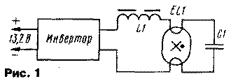
Encyclopedia of radio electronics and electrical engineering / Lighting The described device is designed to power fluorescent lamps when illuminating a garage, garden house or other small spaces. It is made on accessible elements and can be easily repeated by medium-skilled radio amateurs. The advantages of the device, in particular, include its ability to operate at a supply voltage reduced to 5 V. Recent studies have shown that when fluorescent lamps are fed with a high (> 20 kHz) frequency current, their luminous efficiency significantly increases (see the article by S. D. Rudyk, V. E. Turchaninov, S. N. Florentsev "High-frequency voltage converter with high input power factor for powering a fluorescent lamp. "- Electrical Engineering, 1996, No. 4, pp. 31 - 33). So for compact lamps with a power of up to 50 W, it reaches 26 ... 35%. This happens mainly due to a decrease in near-electrode power losses. When the lamps are pulsed with high-frequency currents, they decrease by two to three times. The converter developed by the author is designed to power LBU-30 fluorescent lamps with a power of 30 W and has the following technical characteristics: nominal supply voltage - 13,2 V; rated input current - 2,6 A; conversion frequency - 20...25 kHz; The efficiency of the device is 85%. The block diagram of the converter is shown in fig. 1. It is made on the basis of a voltage inverter loaded on a series oscillatory circuit formed by an inductor L1 and a capacitor C1, in parallel with which a fluorescent lamp EL1 is connected.
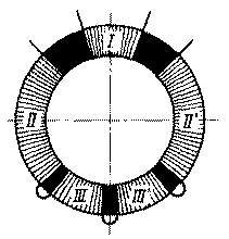
The inverter converts the DC battery voltage of 13,2 V into AC, in the form of rectangular pulses with an amplitude of 150 V, supplied to the series oscillatory circuit L1C1. The resonant frequency of the circuit is equal to the frequency of the supply voltage, and the current flowing through the load connected to the circuit capacitor does not depend on its resistance. At the same time, at the moment the supply voltage is applied, the resistance of the lamp EL1 is high, a high voltage is applied to the capacitor C1, and a current exceeding the nominal value flows through the inductor L1. This current also flows through the filaments EL1, heating them up, which ensures reliable switching on of the lamp. When the lamp lights up, its resistance drops and shunts the capacitor C1. As a result, the voltage on it drops to a value that keeps the lamp burning, and the current through the inductor L1 decreases to the nominal value. The circuit diagram of the converter is shown in fig. 2. The oscillatory circuit is formed by elements 12, C7. The inverter is made according to the scheme of a push-pull oscillator with positive current feedback (POST) on the elements T1, T2, L1, VT1, VT2, VD1-VD6, C2-C5, R1-R4. This construction of the inverter allows you to minimize the energy spent on controlling the key transistors VT1, VT2, and reduce the effect of the power supply voltage on the stability of the converter. In this case, optimal conversion frequencies are also easily provided. In addition to the above elements, the converter contains a fuse FU1, a capacitor C1 that protects the power supply from surge currents, and a C6R5 circuit that suppresses high-frequency voltage fluctuations on the windings of the transformer T2. The converter works as follows. At the moment the supply voltage is applied, the transistors VT1, VT2 are closed and the voltage on their collectors is equal to the supply voltage. A current flows through resistors R1, R2, charging capacitors C2, C3 in the direction opposite to their polarity indicated in the diagram. After some time, the voltage at the base of one of the transistors (for example, VT1) will reach its opening threshold and a current will flow through the collector circuit, which will also pass through the power source, winding I of transformer T2 and winding III of transformer T1. As a result, a current will also appear in the winding II of the transformer T1, which, in turn, will flow through the capacitor C2 and the base-emitter junction of the transistor VT1. In this case, VT1 enters saturation mode, and capacitor C2 is recharged in accordance with the polarity indicated in the diagram. Its recharge is limited by the diode VD1. Thus, the converter is started. Transistor VT1 will be in saturation until the base current stops, which can occur as a result of a decrease in current through the primary winding of transformer T2 or a short circuit of the windings of transformer T1. The converter starts at the resonant frequency of the circuit L2C7, and transistors VT1, VT2 will switch at the moment the current of the inductor L2 passes through zero. After the lamp EL1 is ignited and the capacitor C7 is shunted by it, the energy transfer of the inductor L2 to the lamp and capacitor C7 is delayed and the conversion frequency is reduced. In this case, its stabilization occurs at a level determined by the magnetization reversal time of the inductor L1, which, saturating, short-circuits the winding of the transformer T1, which leads to the closing of one transistor and the opening of another. The tuning frequency of the oscillatory circuit is chosen equal to 46 kHz, and the operating frequency of the converter is 20.. .25 kHz. With this ratio of frequencies, maximum efficiency is ensured. Chains C4VD5R3 and C5VD6R4 serve to reduce the amplitude of the switching pulse on the collectors of transistors VT1, VT2 when they are closed. The converter is mounted on a printed circuit board made of foil fiberglass with dimensions of 200x50 mm. It can be built into the luminaire or housed in a separate housing. When mounting the L1 inductor and the T1 transformer, it is desirable to place it as far as possible from the T2 transformer and the L2 inductor, and the oxide capacitors C2, C3 should not be placed in close proximity to the transistors VT1, VT2 and resistor R5. The converter uses MLT resistors, capacitors K73-17 (C1, C4, C5) for a voltage of 63 V, K50-35 (C2, C3) for a voltage of 25 V and K15-5 (C6, C7) for a voltage of 1,6 kV. Transistors KT803A can be replaced by KT908 with any letter index. It is desirable to choose them with the same base current transfer coefficient. Each transistor is mounted on a heat sink with an area of 50 cm2. The KD105 diodes used in the device can have any letter index. Other low-frequency diodes with a permissible forward current of at least 0,5 A are also suitable. Diodes KD212 (VD3 - VD6) can also be with any letter index. It is permissible to replace them with other silicon ones capable of operating at frequencies up to 50 kHz and allowing a forward current of at least 2 A and a reverse voltage of at least 50 V. Chokes and transformers are wound on ring magnetic cores made of M2000NM-1 ferrite. The windings of the chokes L1, L2 are placed on the magnetic circuits K7x4x2 and K40x25x11 and contain 5 turns of wire PEV-2 0,63 and 140 turns of wire PEV-2 0,41, respectively. The windings of transformers T1, T2 are wound on magnetic cores K20x12x6 and K40x25x11, respectively. The windings I, III and III' of the transformer T1 contain 3 turns of wire PEV-2 0,63, and II and II' - 12 turns of wire PEV-2 0,41 each. Each of the windings I and I' of the transformer T2 consists of 11 turns of PEV-2 0,8 wire, and the winding II consists of 140 turns of PEV-2 0,41 wire. Windings I and I' of transformer T2 are wound simultaneously in two wires over winding II. Lakotkan should be laid between the windings. The windings of the transformer T1 must be arranged in accordance with the diagram shown in fig. 3. Winding I must be placed symmetrically with respect to the other windings in order to ensure the symmetry of the half-cycles of the output voltage and to exclude one-sided saturation of the transformer magnetic circuit, which leads to an increase in energy losses. Choke L2 must have a non-magnetic gap. To do this, in its core, before winding, you need to make a cut with a width of 0,8 mm.
For the time of establishing the converter, instead of the lamp EL1 and the capacitor C7, a resistor with a resistance of 2 kOhm and a power of 1 ... 5 W is connected in series with the inductor L10. First, check the reliability of starting the converter. To do this, a supply voltage of 5 V is applied to it and, if it does not start generating rectangular pulses with a frequency of 20 ... 25 kHz, the resistance of the resistors R1, R2 is reduced, but not more than three times. Next, control the generation frequency of the converter. To do this, it is supplied with a nominal supply voltage of 13,2 Vis using an oscilloscope or frequency meter to determine the frequency of the alternating voltage on the windings of the transformer T2. If it goes beyond 20 ... 25 kHz, change the number of turns of the inductor L1. To increase the frequency, decrease it, and to decrease it, increase it. After that, the output circuits of the converter are restored and, in series with the inductor L2, a resistor with a resistance of 10 Ohms and a power of 0,5 ... 1,0 W is connected. Then, the nominal supply voltage is applied to the converter, and after the EL1 lamp lights up, using an oscilloscope, the voltage shape on the newly installed resistor is monitored: it should be close to sinusoidal. The current through the inductor L2 should be about 0,22 A. When power is supplied to the converter, the lamp should light up no later than 1 ... 2 s. In addition to the LBU-30 lamp, others designed for the same voltage and current, for example, LB-40, can work together with the described converter. Author: L. Zuev, Dzerzhinsk, Nizhny Novgorod region; Publication: N. Bolshakov, rf.atnn.ru
Air trap for insects
01.05.2024 The threat of space debris to the Earth's magnetic field
01.05.2024 Solidification of bulk substances
30.04.2024
▪ The world's first mine hydroelectric power station was launched ▪ Philips Xenium E580 Super Standalone Mobile Phone ▪ LG to buy LCD panels from Sharp ▪ The timing and quality of sleep varies by gender.
▪ site section Batteries, chargers. Article selection ▪ article Lord Tashkenters. Popular expression ▪ article What is a pomegranate? Detailed answer ▪ article Mechanic of the vodka bottling shop. Job description ▪ article Automotive tachometer. Encyclopedia of radio electronics and electrical engineering ▪ article FM transistor converter. Encyclopedia of radio electronics and electrical engineering
Home page | Library | Articles | Website map | Site Reviews www.diagram.com.ua |


 Arabic
 Bengali
 Chinese
 English
 French
 German
 Hebrew
 Hindi
Hindi Italian
 Japanese
 Korean
 Malay
Malay Polish
 Portuguese
 Spanish
 Turkish
 Ukrainian
 Vietnamese


 Leave your comment on this article: